Maasal cervical dilator

a cervical dilator and mammalian technology, applied in the field of mammalian cervical dilators, can solve the problems of requiring more than twenty minutes, time-consuming one-by-one dilation, and uterine wall perforation, so as to facilitate cervix insertion and avoid cervix trauma

Inactive Publication Date: 2008-02-14
SHAHER MAASAL +1
View PDF8 Cites 80 Cited by
  • Summary
  • Abstract
  • Description
  • Claims
  • Application Information

AI Technical Summary

Benefits of technology

[0008]The contoured panels that form the malecot are coupled to an elongated central control rod, which runs through the length of the panels and the insertion depth limiter. The control rod acts as part of a transmission mechanism, which converts linear or rotational movement of the control rod (or rotation of a thumb nut threaded onto the rod) into radial displacement of the contoured panels. In a preferred embodiment, the contoured panels are attached to the control rod by swing arms that are pivotally attached to both the control rod and the panels such that linear displacement of the control rod along its axis, causes the swing arm to fold outwardly, which in turn causes the panels to expand radially away from the control rod.
[0009]The distal end of the expandable malecot is rounded or blunted and smooth to facilitate cervix insertion and to avoid trauma to the cervix. In one embodiment, swing arms that enable expansion of the malecot panel can themselves be rounded to provide the rounded distal end.

Problems solved by technology

A problem with the prior art methods and prior art cervical dilation devices is the risk of perforating the uterine wall.
Moreover, cervical dilation using prior several-different diameter art probes, one-by-one is time-consuming.
Cervical dilation using prior art probes can easily require more than twenty minutes to perform, prolonging the time required to perform an intra-uterine procedure.

Method used


Image

  • Maasal cervical dilator
  • Maasal cervical dilator
  • Maasal cervical dilator

Examples


Embodiment Construction

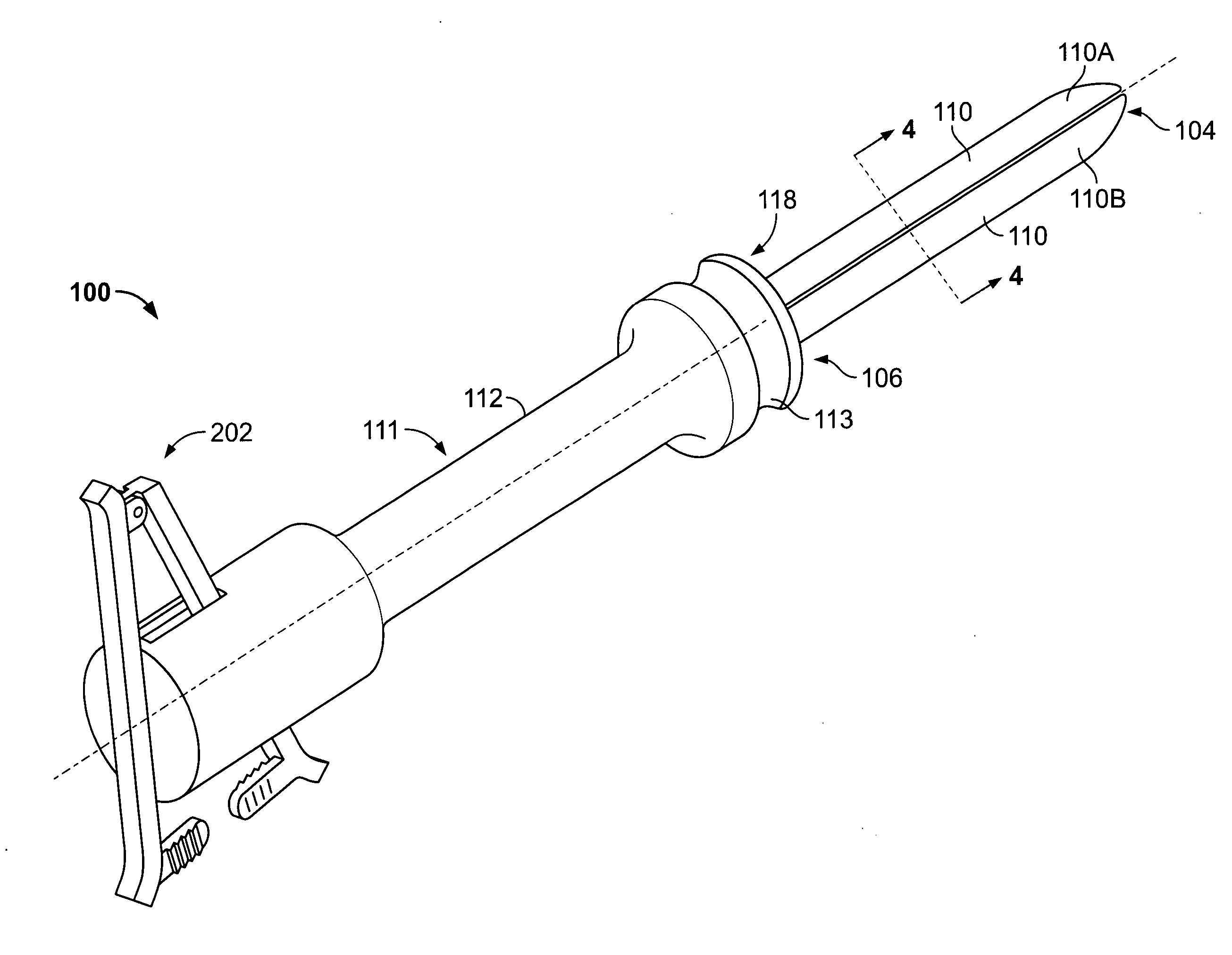
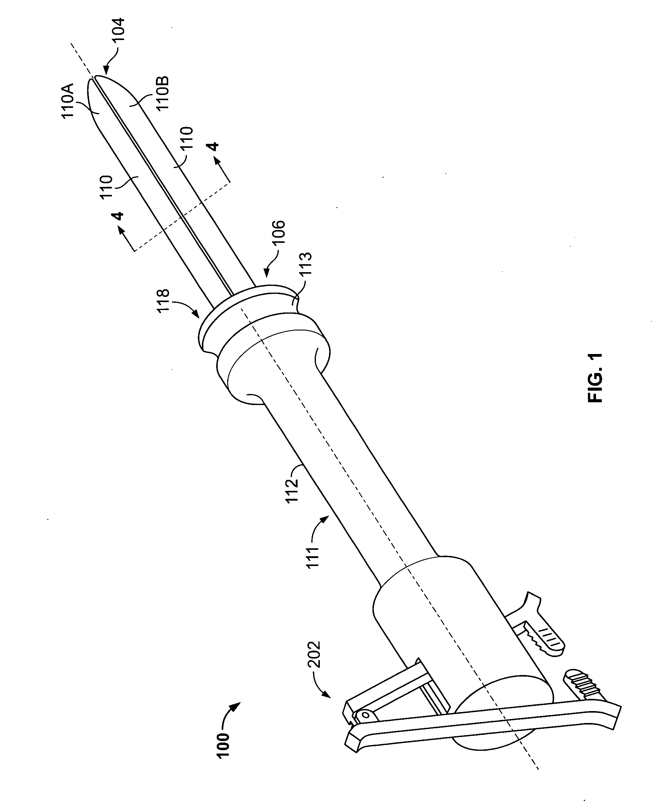
[0020]FIG. 1 shows a perspective view of a Maasal cervical dilator 100 according to one embodiment of the invention claimed herein. The dilator 100 is comprised of a thin and elongated dilating element embodied as dilating malecot 110 and an insertion depth limiter 112, which has an intermediate portion 111 that is narrowed to provide a grip for a user. The malecot 110 is in turn comprised of first and second elongated and contoured deflection panels 110A and 110B, which can be expanded away from each other as described below.

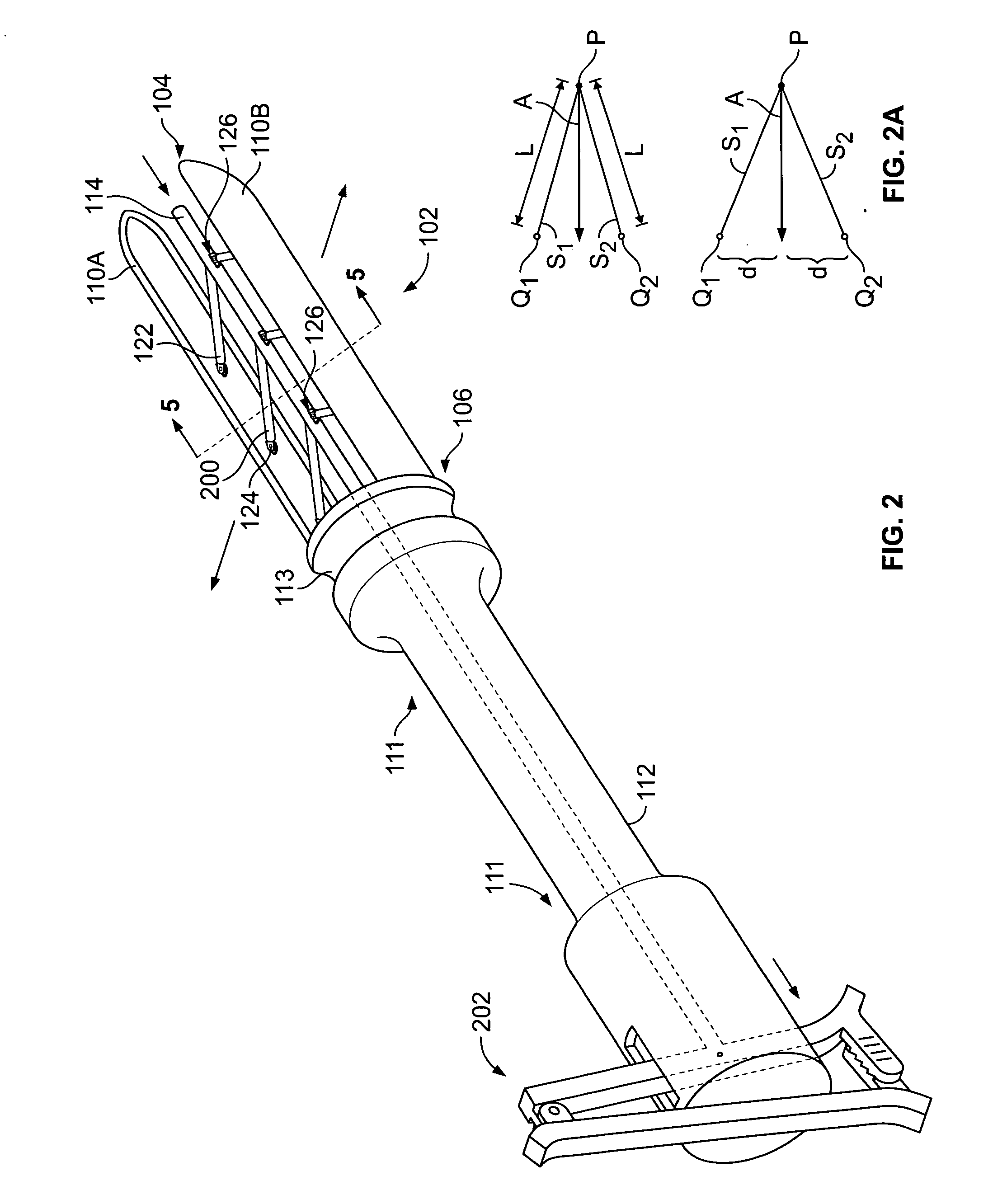
[0021]The malecot 110 has a rounded or tapered distal end 103, shaped as such to facilitate insertion of the malecot 110 and to avoid trauma to the cervix and cervical of the uterus as shown in FIG. 3. The rounded distal end 104 of the malecot is provided by rounding the distal end 104 of each of the contoured deflection panels 110A and 110B. In an alternate embodiment, a tapered and smoothened end is provided by modifying the distal set of the swing arms, 122,...


PUM


Abstract

Opposing, contoured panels are controllably opened by either a translational or rotational movement of a driving control rod to controllably open or dilate a cervix. An insertion depth limiter, prevents over-insertion of the panels into the uterus thereby preventing accidental perforation of the uterine wall. The device can be straight, curved or articulated to accommodate anatomical differences.

Description

RELATED APPLICATIONS[0001]This application claims the filing benefit of, and incorporates by reference, U.S. provisional patent application for “Maasal Dilator,” which was filed Aug. 8, 2006, and which is identified by patent application Ser. No. 60 / 836,337.BACKGROUND OF THE INVENTION[0002]Many gynecological procedures require the cervix to be dilated or opened. In the prior art, cervical dilation is accomplished by inserting progressively larger-diameter probes, one-by-one into the cervix. A very small is inserted first, which causes the cervix to open by a correspondingly small amount. As is known, the cervix opens gradually.[0003]After a very small probe is inserted, a slightly larger probe is inserted to cause the cervix to dilate further. One-by-one, progressively larger probes are inserted, with each probe causing the cervix to dilate further. By inserting increasingly larger diameter probes, the cervix is eventually dilated to the diameter required to access the interior of t...

Claims


Application Information

Patent Timeline
Patent Type & Authority Applications(United States)
IPC IPC(8): A61B17/42A61M29/00
CPCA61B17/0206A61M29/02A61B17/42
Inventor SHAHER, MAASALSHAHER, AHMAD
Owner SHAHER MAASAL
Why Eureka
Try Eureka