Method for Adjusting the Transfer of Printing Ink

a technology of printing ink and transfer rate, which is applied in the direction of office printing, printing, rotary presses, etc., to achieve the effects of reducing the capacity of screen rollers, preventing waste, and increasing the production speed of printing presses

Inactive Publication Date: 2008-02-21
KOENIG & BAUER AG
View PDF15 Cites 7 Cited by
  • Summary
  • Abstract
  • Description
  • Claims
  • Application Information

AI Technical Summary

Benefits of technology

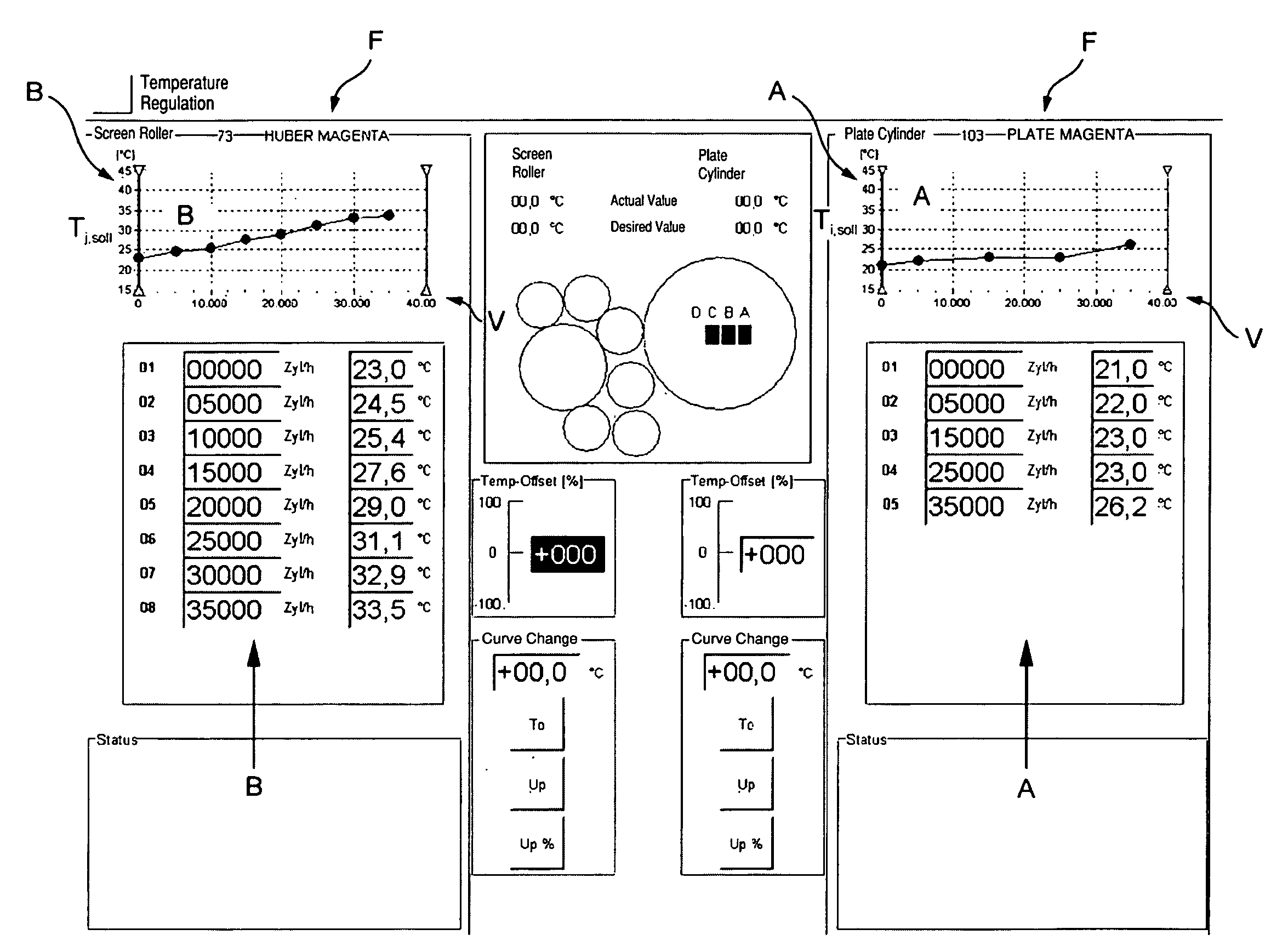
[0016] It is moreover advantageous that a conveying rate of a screen roller, which picks up printing ink from a reservoir and which transfers it to an adjoining rotating body, can be kept at least approximately constant. In the case of an increase in the production speed of the printing press, as constant as possible an amount of ink is conveyed to the material to be imprinted, in spite of the reduction of the capability of the screen roller for the transfer of printing ink occurring along with this, because of an increasingly incomplete emptying of the screen roller's small cups. On the other hand, by a regulation of the temperature at the shell face of the forme cylinder in particular, which temperature regulation is dependent on the production speed of the printing press, the value of the tackiness of the printing ink that is transported by the forme cylinder is maintained in a range suitable for the printing process. Plucking of the printing ink at the surface of the material to be imprinted, in particular, is thus prevented. The printing ink is matched, in regard to its splitting and holding capabilities, as a function of the production speed of the printing press by a setting, which meets the requirements, of its temperature to the actually occurring printing process. The setting of its temperature takes place indirectly by setting the temperature at the shell face of a rotating body which is conducting this printing ink. To prevent waste, because of inappropriate temperature-dependent properties of the ink used for printing, and typically occurring in the course of an intended change of the production speed of the printing press, the different chronological behavior for performing the adaptation to the temperature of the printing ink and for performing the adaptation of the production speed of the printing press are taken into consideration. The possibility of changing a condition of the press, for example manually, within defined limits is also considered. In this way performing a fine adjustment, directed to the provision of a good quality of the printed product, can be accomplished. All these measures contribute to maintaining the quality of a product which is produced by the printing press on a high level in spite of a change in the production speed of the printing press.

Problems solved by technology

In the case of an increase in the production speed of the printing press, as constant as possible an amount of ink is conveyed to the material to be imprinted, in spite of the reduction of the capability of the screen roller for the transfer of printing ink occurring along with this, because of an increasingly incomplete emptying of the screen roller's small cups.

Method used


Image

  • Method for Adjusting the Transfer of Printing Ink
  • Method for Adjusting the Transfer of Printing Ink
  • Method for Adjusting the Transfer of Printing Ink

Examples


first embodiment

[0121] In the first embodiment, as shown in FIG. 12 a direct use of the warm return flow, for example of a maximum temperature of 35 to 40° C., and in particular, of apprx. 38° C., takes place from the circuit K3 for temperature-regulating the drive mechanisms M, for example by the use of a fluid-gas heat exchanger 119, such as, for example, a heat exchanger heating register, for direct heating of the air during winter operations.

second embodiment

[0122] In the second embodiment, as depicted in FIG. 13 a use of the temperature-regulating medium from the circuit K2 takes place as a heat source for a heat pump 121. By the use of the heat pump 121, it is possible to reach a higher temperature level in a reservoir 122, for example up to 55° C., than in the embodiment in accordance with FIG. 12, but an additional structural and energy layout becomes necessary.

[0123] The two regeneration concepts represented in FIGS. 12 and 13 can also make use of the respectively other source, such as K2 or K3 for example, in FIG. 12, of the return flow from K2, and in FIG. 13 of the return flow from K3. The systems can also have recourse to the heat flow 63, as may be seen in connection with FIG. 5 as the source.


PUM


Abstract

Transfer of printing ink is adjusted using a first roller in an inking unit of a printing machine, which transfers ink to a forme cylinder. A temperature control unit enables an outer surface of the first roller to reach a required temperature and / or to enable an outer surface of the forme cylinder to reach the required temperature. That temperature control unit can be either controlled or regulated by an adjusting device. Specific curves or reference points for an interrelationship between a production speed of a printing machine and the respective required temperature on the outer surface of the forme cylinder, or on the outer surface of the first roller are stored in a storage unit of the adjusting device for various printing inks or ink types.

Description

CROSS-REFERENCE TO RELATED APPLICATIONS [0001] This application is the U.S. national phase, under 35 USC 371, of PCT / EP2005 / 057231, filed Dec. 30, 2005; published as WO 2006 / 072559 A1 on Jul. 13, 2006 and claiming priority to DE 10 2005 000 856.9, filed Jan. 5, 2005; to DE 10 2005 005 303.3, filed Feb. 4, 2005 and to PCT / EP2005 / 052287, filed May 18, 2005, the disclosures of which are expressly incorporated herein by reference. FIELD OF THE INVENTION [0002] The present invention is directed to a method for regulating the transfer of printing ink. A first roller is arranged in an inking system of a printing press and transfers ink to a forme cylinder. A desired temperature is set by a temperature regulating device of the first roller on the first roller's surface. A desired temperature is also set on the surface of the forme cylinder by a forme cylinder temperature regulating device. The temperature regulating devices are controlled or are regulated by an adjusting device. BACKGROUND ...

Claims


Application Information

Patent Timeline
Patent Type & Authority Applications(United States)
IPC IPC(8): B41F23/04
CPCB41F31/002B41F13/22
Inventor SCHNEIDER, GEORGREDER, WOLFGANG OTTO
Owner KOENIG & BAUER AG
Why Eureka
Try Eureka