

Layered scavenging carburetor
- Summary
- Abstract
- Description
- Claims
- Application Information
AI Technical Summary
Problems solved by technology
Method used
Image

Examples
first embodiment
of Valve
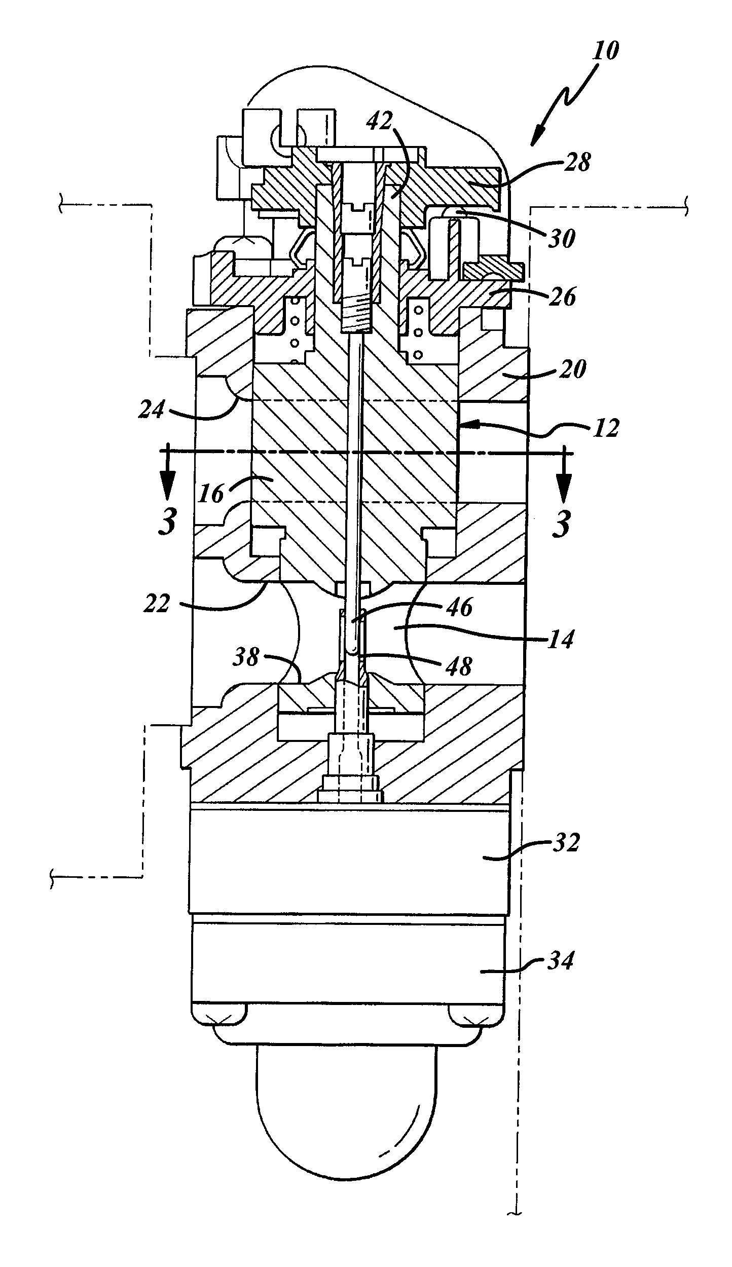
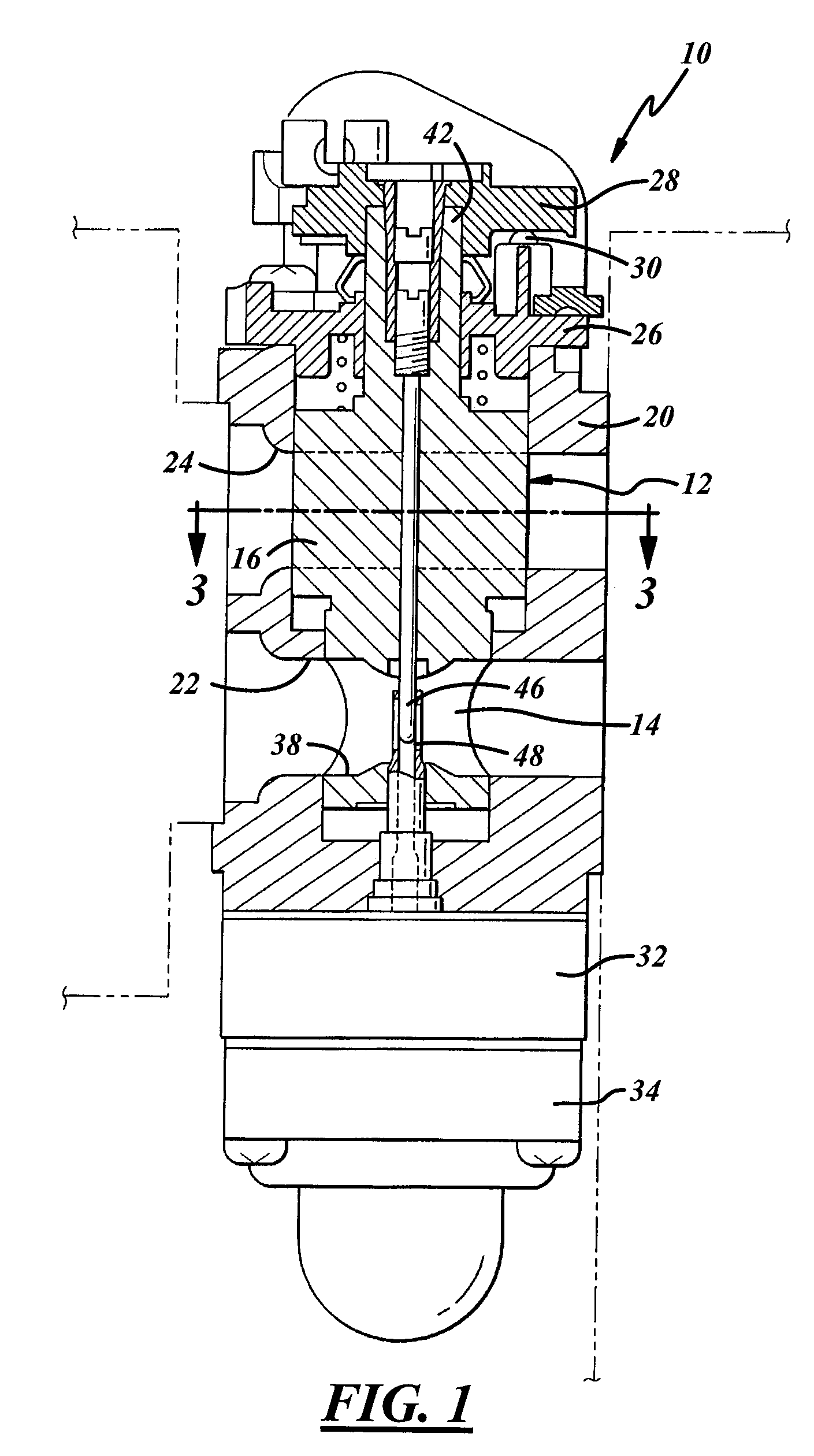
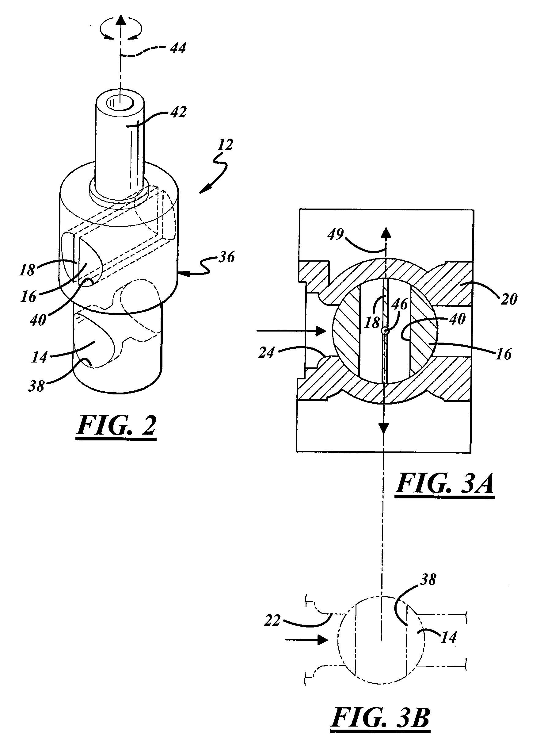
[0023]The valve 12 regulates fluid-flow through the carburetor 10 and to the associated internal combustion engine by permitting flow when the valve is open, preventing or substantially restricting flow when it is closed, and permitting partial flow therebetween. Referring to FIG. 2, in this embodiment a valve body 36 may be constructed out of one-piece, or composed of multiple pieces. The throttle valve 14 may be formed in a lower, smaller-diameter portion of the valve body 36, and the air valve 16 may be formed in an upper, larger-diameter portion of the valve body. The different valves each have a generally cylindrical shape that each define a center axis that may be parallel to each other. As shown here, both the throttle valve 14 and the air valve 16 are of the rotary type and thus are rotated to open and closed positions. The throttle valve 14 and the air valve 16 permit fluid-flow when the valves are open, prevent or substantially restrict flow when the valves are clo...
second embodiment
of Valve
[0029]FIGS. 7A and 7B show a second embodiment of a valve 112. This embodiment is similar to the first embodiment in many respects, and the similarities will not be repeated here. One difference is a baffle 118. The baffle 118 can be fixed in an air valve 116 and particularly in an air bore 140. The air bore 140 extends axially from a first end 150 to a second end 152, and the baffle 118 extends from a first end 154 to a second end 156. In this embodiment, the baffle 118 is not coextensive with the air bore 140. Instead, the first end 154 and the second end 156 of the baffle 118 are located within and away from the first end 150 and the second end 152 of the air bore 140, leaving voids such as a first gap 158 defined by the respective first ends, and a second gap 160 defined by the respective second ends. The baffle 118 may still lie along a center axis of the air bore 140 and may divide it into two equal sections or may be positioned otherwise as desired.
[0030]When in use, ...
third embodiment
of Valve
[0031]FIG. 8 shows a third embodiment of a valve. This embodiment is similar to the first embodiment in many respects, and the similarities will not be repeated here. One difference is a baffle 218. Although not shown, the baffle 218 may be fixed in an air valve, and particularly in an air bore that extends from a first end to a second end. The baffle 218 extends from a first end 254 to a second end 256. In this embodiment, the baffle 218 may define one or more voids or cutouts in its periphery. For example, a first cutout 262 may be carved in the first end 254 and a second cutout 264 may be carved in the second end 256; as shown by phantom, other cutouts may be carved on other sides of the baffle 218. Without the first and second cutouts 262 and 264, the baffle 218 would be coextensive with the first and second end of the air bore. The cutouts themselves can also take numerous shapes and sizes other than the ones shown. The first and second cutouts 262 and 264 respectively ...
PUM
| Property | Measurement | Unit |
|---|---|---|
| closing movements | aaaaa | aaaaa |
| speed | aaaaa | aaaaa |
| pressure | aaaaa | aaaaa |
Abstract
Description
Claims
Application Information