Joint Hose Slippage Prevention Apparatus

Inactive Publication Date: 2008-02-21
WORKS BELL
View PDF0 Cites 17 Cited by
  • Summary
  • Abstract
  • Description
  • Claims
  • Application Information

AI Technical Summary

Benefits of technology

[0028]Consequently, the necessity of welding or piercing work at a position for attachment of the tension stay can be eliminated, whereby

Problems solved by technology

In general, the suction pipe extending from the compressor and the suction

Method used


Image

  • Joint Hose Slippage Prevention Apparatus
  • Joint Hose Slippage Prevention Apparatus
  • Joint Hose Slippage Prevention Apparatus

Examples


Example

First Embodiment

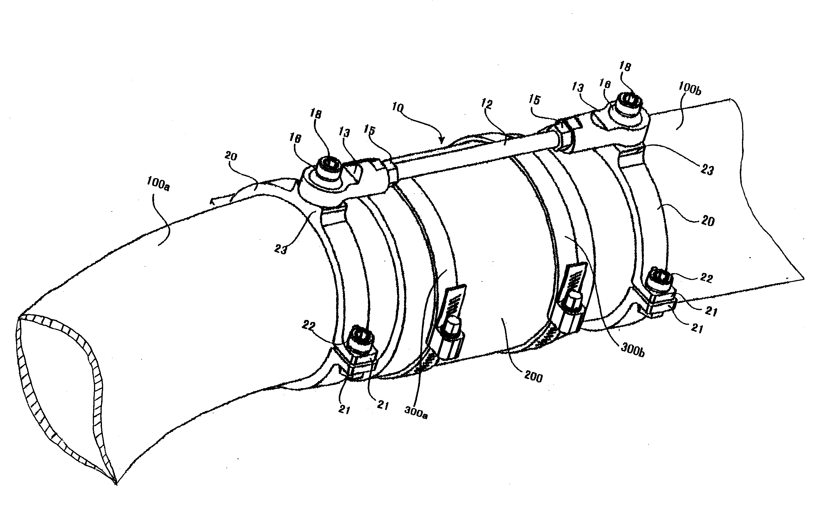
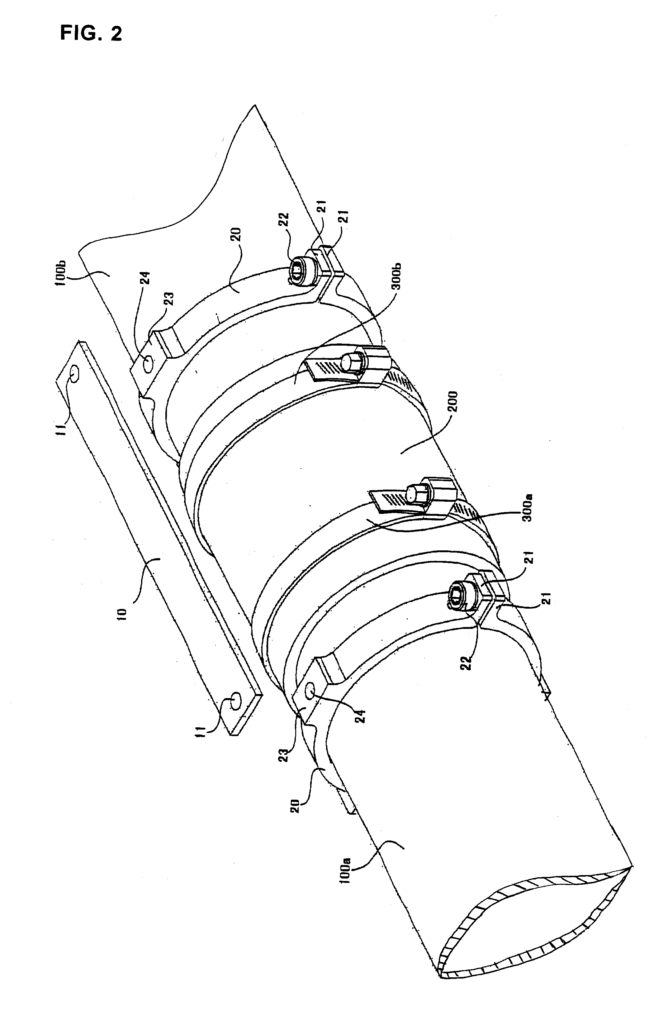
[0037]First, a joint hose slippage prevention apparatus of a first embodiment will be described with reference to FIG. 2. FIG. 2 is a perspective view illustrating the joint hose slippage prevention apparatus of the first embodiment.

[0038]As shown in FIG. 2, an opening of the suction pipe 100a extending from the compressor is covered with one end of the joint hose 200. An opening of the suction pipe 100b extending from the throttle body is covered with the other end of the joint hose 200.

[0039]The joint hose 200 has a shape of a cylinder composed of silicone or urethane. Through the joint hose 200, continuity is achieved between the suction pipe 100a extending from the compressor and the suction pipe 100b extending from the throttle body.

[0040]The suction pipe 100a extending from the compressor is fastened with the hose band 300a over the joint hose 200, while the suction pipe 100b extending from the throttle body is fastened with the hose band 300b over the joint ho...

Example

Second Embodiment

[0054]Next, a joint hose slippage prevention apparatus of a second embodiment will be described with reference to FIG. 3 and FIG. 4. FIG. 3 is a perspective view illustrating the joint hose slippage prevention apparatus in the second embodiment, and FIG. 4 is a cross-sectional view of the joint hose slippage prevention apparatus in the second embodiment.

[0055]The joint hose slippage prevention apparatus of this embodiment is especially favorable in a case where the suction pipe 100a and the suction pipe 100b are deviated in a facing position relation. Since the joint hose 200 is composed of silicone, urethane and the like, the joint hose transforms to cover both the suction pipes 100a and 100b and achieve continuity therebetween.

[0056]The tension stay 10 of the joint hose slippage prevention apparatus according to the second embodiment has rod end bearings 13 at both the ends of a rod 12, respectively.

[0057]A groove is provided on the outer circumference surface at ...

Example

Third Embodiment

[0064]Next, a joint hose slippage prevention apparatus of a third embodiment will be described with reference to FIG. 5 and FIG. 6. FIG. 5 is a perspective view showing a clamp member 120 on the throttle body side of the joint hose slippage prevention apparatus in the third embodiment.

[0065]The clamp member 120 on the throttle body side has a shape of a flat plate bent into an L-letter shape, and two planes thereof are substantially orthogonal. One of the planes functions as an attachment plane 120a attached to a throttle body 500, and the other plane functions as a fasten plane 120b fastened to the tension stay 10.

[0066]Two screw holes 125 are pierced on the attachment plane 120a. A space between the screw holes 125 is equal to a space between screw holes drilled on a throttle body attachment plane 450 for attachment of a throttle body 500, the plane 450 being placed on an intake manifold 400.

[0067]The fasten plane 120b is provided with a screw hole 124 into which t...


PUM


Abstract

The present invention provides a joint hose slippage prevention apparatus for preventing slippage of a joint hose connecting a suction pipe extending from a compressor and a suction pipe extending from a throttle body. The joint hose slippage prevention apparatus comprises a tension stay that fastens the compressor side and throttle body side, with ends connected to the compressor side and the throttle body side. Consequently, when the compressor side and throttle side almost separate from each other, they are held down by the tensile strength of the tension stay, whereby the relative positional relation between the compressor side and throttle side is maintained. Accordingly, it is possible to prevent the joint hose from slipping off.

Description

BACKGROUND OF THE INVENTION[0001]1. Field of the Invention[0002]The present invention relates to a joint hose slippage prevention apparatus for preventing slippage of a joint hose connecting a suction pipe extending from a compressor and a suction pipe extending from a throttle body.[0003]2. Description of the Related Art[0004]The engine of an automobile is an internal combustion system that repeats processes for sucking and compressing a mixed gas of oxygen and fuel, exploding the mixed gas, exhausting, etc. and converts the output obtained through these processes into driving force. A plurality of cylinders is installed inside the engine to be an internal combustion chamber. The capacity of the cylinder is a basic factor in determining the output.[0005]Since the capacity of the cylinder is constant, a supercharging device may be installed in the suction system in order to obtain higher output.[0006]The supercharging device is a turbo charger, a super charger, etc., which utilize t...

Claims


Application Information

Patent Timeline
IPC IPC(8): F16L3/00
CPCF02M35/10144F16L2201/20F16L33/02F16L27/107
Inventor ICHIKAWA, YASUAKI
Owner WORKS BELL
Why Eureka
Try Eureka