Method for Detecting Operating Parameters of a Power Tool Comprising an Internal Combustion Engine

a technology of power tools and operating parameters, which is applied in the direction of machines/engines, amplifier modifications to reduce noise influence, and apparatus for force/torque/work measurement, etc., can solve the problems of thermal loads, high cost, and complex technology of sensors, and achieve quick determination of crankshaft angle position and crankshaft angle position position. the effect of speeding up the determination speed

Active Publication Date: 2008-02-21
ANDREAS STIHL AG & CO KG
View PDF16 Cites 16 Cited by
  • Summary
  • Abstract
  • Description
  • Claims
  • Application Information

AI Technical Summary

Benefits of technology

[0003]It is an object of the present invention to provide a method for detecting operating states of a reciprocating piston engine which method allows to reduce the number of sensors in an internal combustion engine.
[0011]The plurality of operating parameters to be derived from the alternating voltage signal opens up the possibility to supply in a simple way the operating parameters to a diagnostic and / or servicing device for evaluation wherein operating parameters can be selected and saved in a non-volatile data memory of the diagnostic and servicing device. Such data can be utilized advantageously in a shop for servicing the power tool.
[0012]In an advantageous further embodiment of the method, two interval engine speeds are calculated for each crankshaft angle interval. Because the alternating voltage signal changes its polarity once within each crankshaft angle interval as a result of the pole division of the alternating current generator, there are three zero positions. Each crankshaft angle interval can therefore be divided simply into two zero position intervals so that, for example, six crankshaft angle intervals provide twelve zero position intervals. A zero position interval is determined by the time interval between two sequential zero crossings of the voltage signal. Because of the pole division, a fixed mechanical crankshaft angle spacing between two zero positions is known so that in a simple way, based on the known mechanical spacing of the zero positions and the time interval between neighboring zero positions, the corresponding zero position interval can be calculated relative to an interval engine speed. The zero positions are advantageously determined when the alternator is free of load. For this purpose, the current flow to an electric consumer connected to the alternator is stopped or interrupted at the time a zero crossing occurs. In this way, signal displacements caused by inductivity or capacitance are safely prevented. It was found to be advantageous to keep the alternator load-free in an angle range of from approximately 5° CA before zero crossing to approximately 1° CA after zero crossing, that is to switch off the load, for example.
[0014]The engine speed course of the interval engine speeds can be scanned with regard to a pronounced engine speed minimum for determining a certain crankshaft angle position, for example, the position of the piston at the top dead center. In the crankshaft angle interval of the engine speed minimum, the piston is positioned approximately at top dead center. For a quicker determination of the crankshaft angle position the polarity of the voltage signal in the crankshaft angle interval can be evaluated. For twelve zero crossings, the system can correlate the angle position to the crankshaft for a known zero crossing only within a 30° raster. Accordingly, twelve different crankshaft angle positions are possible. When the direction of the zero crossing, i.e., the polarity of the half wave of the alternating voltage, is additionally taken into account, the twelve zero crossings can be differentiated into six positive and six negative zero crossings, respectively. For a concrete zero crossing, a raster of 60° CA angle correlation is thus possible so that a quicker determination of the crankshaft angle position can be obtained.
[0015]Expediently, the adjustment is chosen such that a zero crossing Oi of the induced alternating voltage signal is preferably approximately 15° CA before top dead center of the piston. In this way, it is ensured that the system can correlate early on the position of the alternating voltage signal to the angle position of the crankshaft so that the starting conditions are improved.

Problems solved by technology

The plurality of sensors is technically complex, expensive, and entails many error sources.
In addition, the required cable arrangement is problematic because in case of small-size power tools with internal combustion engines considerable thermal loads occur.

Method used


Image

  • Method for Detecting Operating Parameters of a Power Tool Comprising an Internal Combustion Engine
  • Method for Detecting Operating Parameters of a Power Tool Comprising an Internal Combustion Engine
  • Method for Detecting Operating Parameters of a Power Tool Comprising an Internal Combustion Engine

Examples


Embodiment Construction

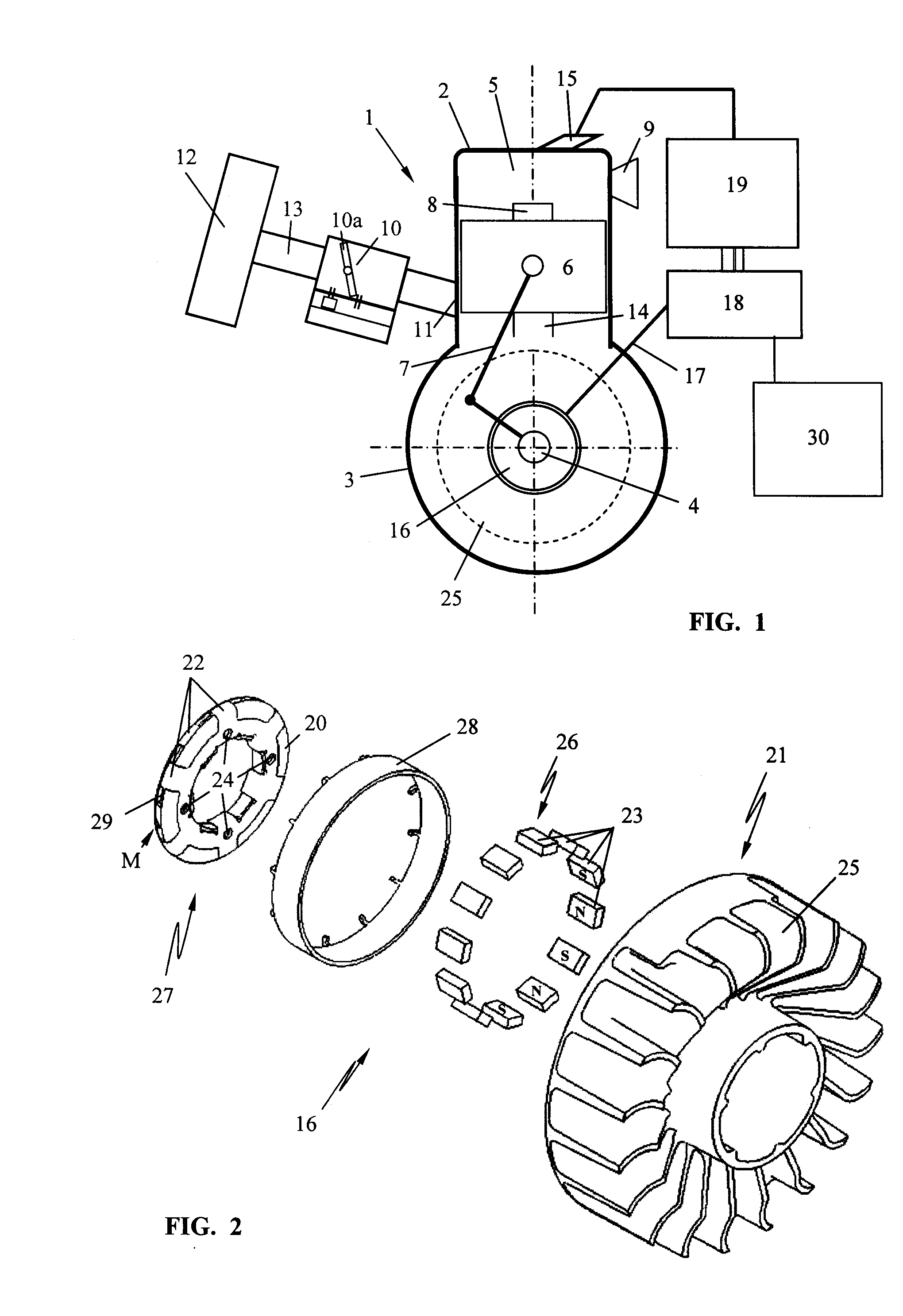
[0034]The schematic illustration of FIG. 1 illustrates a single-cylinder internal combustion engine 1, in particular a two-stroke engine. The method according to the invention is however not limited to the use in a single-cylinder or multi-cylinder two-stroke engine. The method can also be used for detecting operating parameters for a single-cylinder or multi-cylinder four-stroke engine or a similar reciprocating piston engine.

[0035]FIG. 1 shows the internal combustion engine 1 comprised of a cylinder 2 and crankcase 3 in which a crankshaft 4 is supported rotatably. In the cylinder 2 a combustion chamber 5 is formed that is delimited by a reciprocating piston 6. The piston 6 is connected by means of connecting rod 7 to crankshaft 4 in the crankcase 3 and drives the crankshaft 4 in rotation. In the illustrated embodiment, an intake 8 for combustion air opens into the combustion chamber 5 wherein the intake 8 is the port of a transfer passage 14. Moreover, an exhaust 9 is provided thr...


PUM


Abstract

In a method for detecting an operating parameter of a power tool having an internal combustion engine with a cylinder, a piston delimiting a combustion chamber in the cylinder and driving a crankshaft supported rotatably in a crankcase, an intake supplying combustion air to the combustion chamber, an exhaust removing combustion gases from the combustion chamber, and a signal generator driven in rotation by the crankshaft emitting sequential alternating voltage signals, a period duration of the voltage signal is selected to correspond to the n-th portion of a crankshaft revolution with n greater 2. The n-th portion of the crankshaft revolution provides a crankshaft angle interval. For each crankshaft angle interval at least one information is detected that represents a course plotted against the crankshaft angle. The course is scanned with regard to characteristic features that are correlated with an operating parameter of the power tool.

Description

BACKGROUND OF THE INVENTION[0001]The invention relates to a method for detecting an operating parameter of a power tool comprising an internal combustion engine, in particular, of a portable, hand-held power tool with a reciprocating piston engine such as a two-stroke engine, a four-stroke engine or the like. The internal combustion engine comprises at least one cylinder and a crankcase, and a combustion chamber is defined in the cylinder and delimited by a piston, wherein the piston drives in rotation a crankshaft supported rotatably in the crankcase. An intake is provided that supplies combustion air to the combustion chamber and an exhaust is provided for removing combustion gases from the combustion chamber. A signal generator is provided that is driven in rotation by the crankshaft and emits sequential alternating voltage signals for one crankshaft revolution.[0002]Modern internal combustion engines as they are used e.g. in connection with hand-held portable power tools are con...

Claims


Application Information

Patent Timeline
Patent Type & Authority Applications(United States)
IPC IPC(8): G01P3/48
CPCF02D37/02F02D41/0097G01P3/489F02P7/077G01P3/487F02D41/1497
Inventor MAIER, GEORGLAYHER, WOLFGANGABOU-ALY, MOHAMEDLEUFEN, HEINRICHSCHIEBER, EBERHARD
Owner ANDREAS STIHL AG & CO KG
Why Eureka
Try Eureka