
Fixing device, and method and device for heating control used in the same

a technology of fixing device and fixing member, which is applied in the direction of temperatue control, process and machine control, instruments, etc., can solve the problems of melted toner particles adhering to the fixing member, degrading image quality, and reducing image quality, so as to stabilize drive the heating mechanism and reduce errors

Inactive Publication Date: 2008-02-21
RICOH KK
View PDF3 Cites 37 Cited by
  • Summary
  • Abstract
  • Description
  • Claims
  • Application Information

AI Technical Summary

Benefits of technology

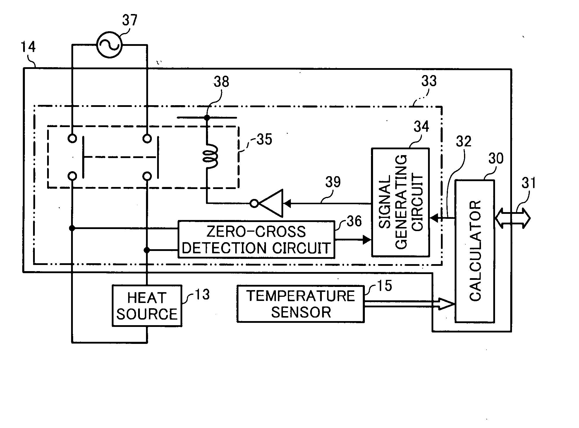
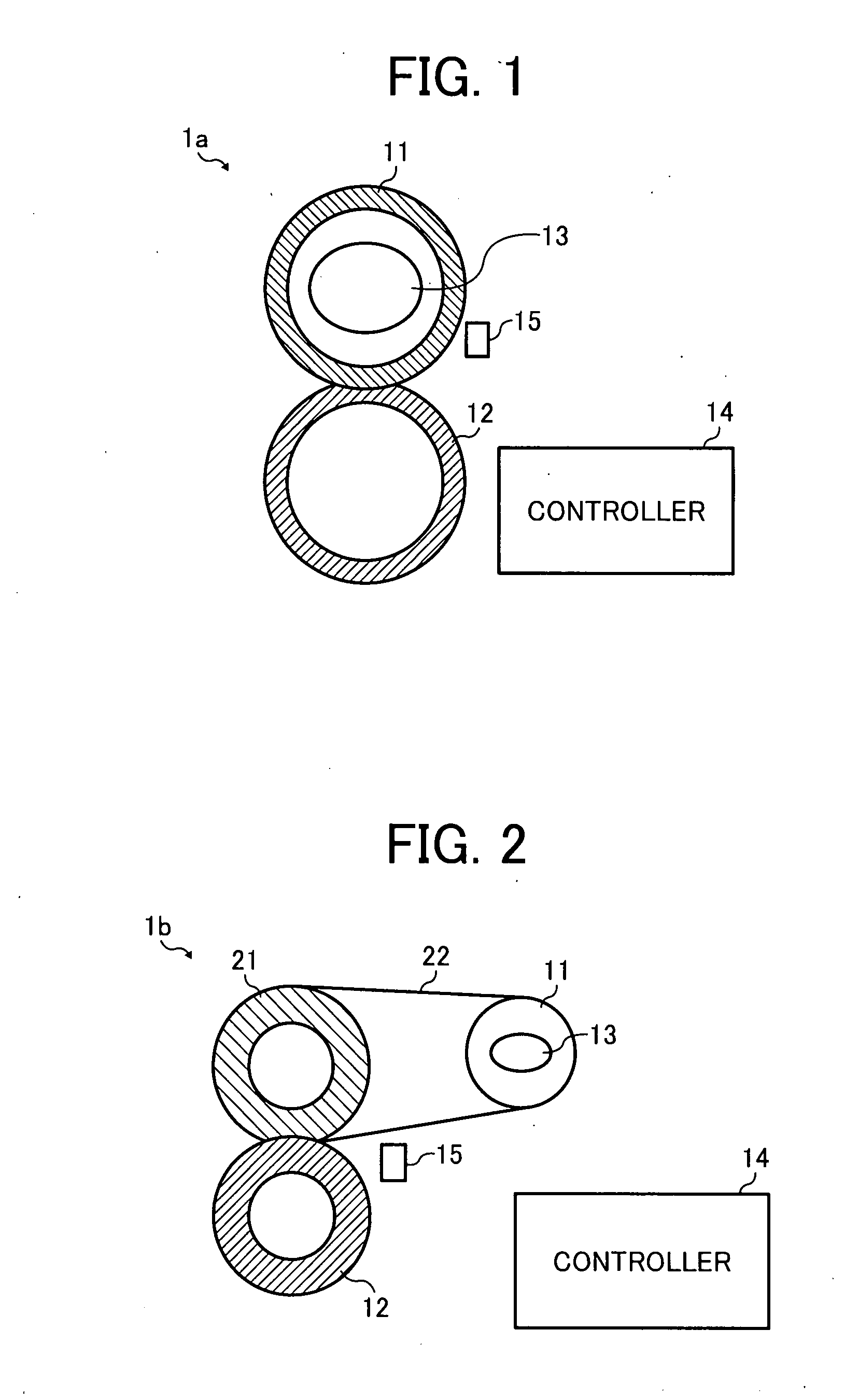
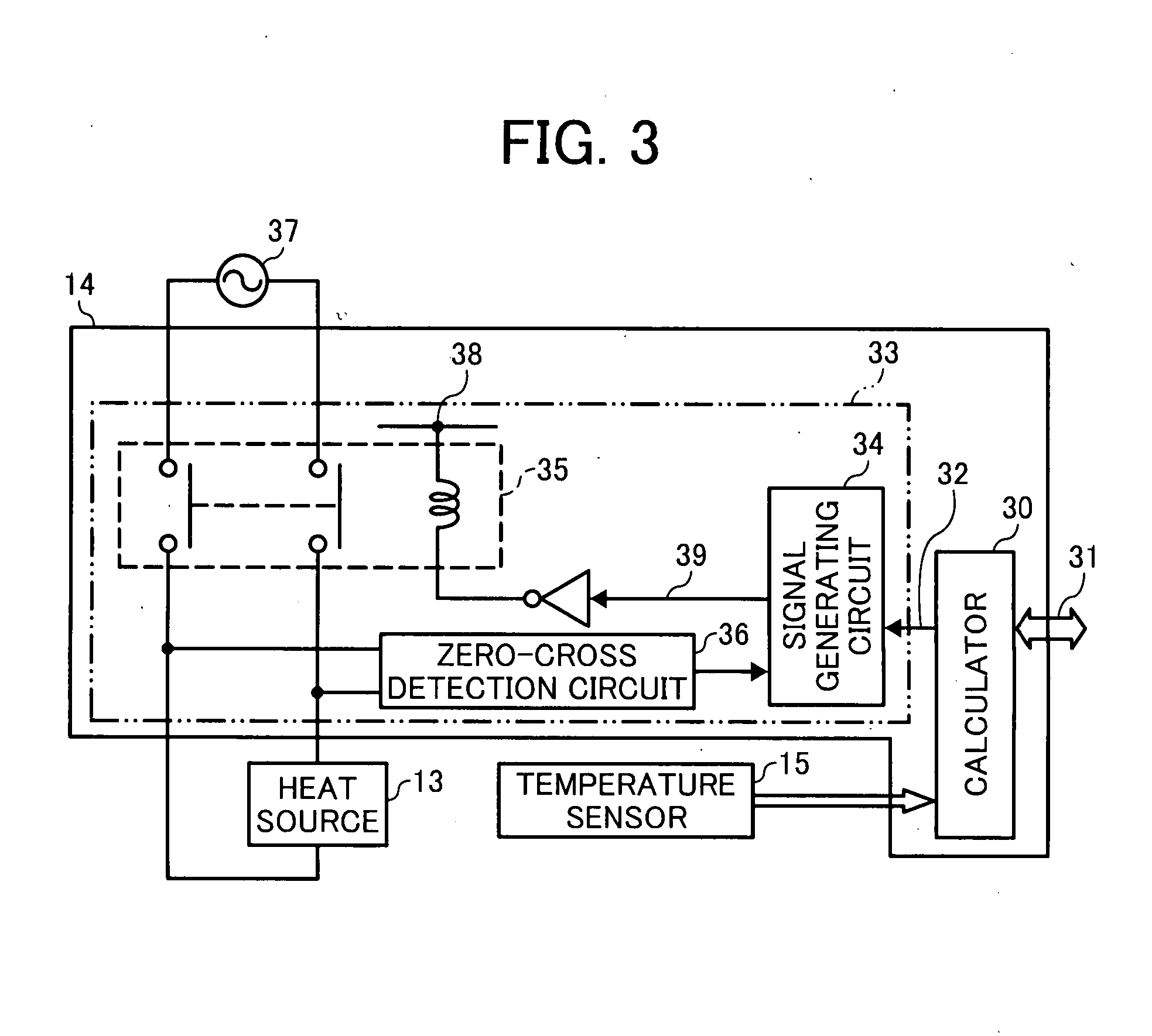
[0032] This patent specification describes, in at least one embodiment, a novel fixing device for controlling a heating mechanism by pulse width modulation that can stably drive the heating mechanism and reduce errors due to unstable operation of the heating mechanism.
[0034] This patent specification further describes, in at least one embodiment, a novel method of controlling a heating device by pulse width modulation that can stably drive the heating device and reduce errors due to unstable operation of the heating device.
[0036] This patent specification further describes, in at least one embodiment, a novel device for controlling a heating device by pulse width modulation that can stably drive the heating device and reduce errors due to unstable operation of the heating device.

Problems solved by technology

In this fixing process, the temperature of the fixing member needs to be adjusted to the desired value because a deviation from the desired value may lead to degradation of image quality.
The degradation of image quality is caused by, for example, adhesion of toner to the fixing member.
When the temperature of the fixing member becomes too high, excessive heat is applied to the layer of toner, causing melted toner particles to adhere to the fixing member.
Furthermore, insufficient melting or unstable fixing of toner on the recording medium may also degrade image quality.
When the temperature of the fixing member becomes too low, the layer of toner is not provided with sufficient heat and fails to stabilize on the recording medium.
Another issue concerning the temperature control of the fixing member relates to a reduction of waiting time.
The on-off control has a drawback since accurate temperature control is difficult due to dead-time, i.e., time delays in transferring heat between components or detecting temperature of the object, for example.
This background temperature control method may fail to eliminate the temperature ripple due to the dead-time that occurs between detection of temperature and driving of the heater when the estimated temperature is substantially deviated from the target value.
Namely, this background temperature control method does not meet the dead-time that is generated throughout the fixing process.
A drawback of this temperature control method is that the dead-time compensation with a model may result in errors due to modeling deficiencies under unexpected conditions, such as a change in dead-time caused by disturbances and a significant error in driving the heater.

Method used


Image

  • Fixing device, and method and device for heating control used in the same
  • Fixing device, and method and device for heating control used in the same
  • Fixing device, and method and device for heating control used in the same

Examples


Embodiment Construction

[0057] It will be understood that if an element or layer is referred to as being “on”, “against”, “connected to” or “coupled to” another element or layer, then it can be directly on, against, connected or coupled to the other element or layer, or intervening elements or layers may be present. In contrast, if an element is referred to as being “directly on”, “directly connected to” or “directly coupled to” another element or layer, then there are no intervening elements or layers present. Like numbers referred to like elements throughout. As used herein, the term “and / or” includes any and all combinations of one or more of the associated listed items.

[0058] Spatially relative terms, such as “beneath”, “below”, “lower”, “above”, “upper” and the like may be used herein for ease of description to describe one element or feature's relationship to another element(s) or feature(s) as illustrated in the figures. It will be understood that the spatially relative terms are intended to encomp...


PUM


Abstract

A fixing device includes a pair of rotating members, a heater, a detector, a calculator, a pulse width modulation circuit, and a controller. In at least one embodiment, the pair of rotating members is configured to fix a toner image on a recording medium. The heater is configured to heat at least one of the pair of rotating members to a process temperature when driven with an alternating current. The detector is configured to detect the process temperature. The calculator is configured to calculate an amount of heat to adjust the process temperature to a reference temperature. The pulse width modulation circuit is configured to generate a drive signal having a pulse width modulation cycle divided into first and second off times and an on time inserted therebetween. The controller is configured to control operation of the heater according to the drive signal.

Description

PRIORITY STATEMENT [0001] The present patent application claims priority under 35 U.S.C. §119 upon Japanese patent application, No. JP2006-146619 filed on May 26, 2006 in the Japan Patent Office, the entire contents of which are hereby incorporated herein by reference in their entirety. BACKGROUND [0002] 1. Field [0003] Example embodiments of the present invention generally relate to a fixing device and / or a method and / or device for heating control used in the same; for example to a fixing device and / or a method and / or device for controlling, by pulse width modulation, a heating mechanism capable of stably driving the heating mechanism and reducing errors due to unstable operation of the heating mechanism. [0004] 2. Discussion of the Background [0005] Typically, an image forming apparatus includes a heating system with a heat source used for a particular purpose. The heating system is provided at a fixing unit, a drying unit, or a data erasing unit of the image forming apparatus and...

Claims


Application Information

Patent Timeline
IPC IPC(8): G03G15/20
CPCG03G2215/2016G03G15/2039G05D23/2418G03G2215/2032G05D23/1913G05D23/24
Inventor SEO, HIROSHIYASUI, MOTOKAZUOGAWA, TADASHIKOIDE, HIROSHI
Owner RICOH KK
Learn More