Fuel cell system and method of operating the same

Inactive Publication Date: 2008-02-21
SAMSUNG SDI CO LTD
View PDF7 Cites 6 Cited by
  • Summary
  • Abstract
  • Description
  • Claims
  • Application Information

AI Technical Summary

Benefits of technology

[0010]Aspects of the present invention provide a fuel cell system that can safely consume a residual fuel remaining in a fuel cell, by controlling the operation of the fuel cell, without any additional load.
[0011]Aspects of the present invention also provide a method of operating the fuel cell system, which can consume residual fuel remaining in the fuel cell.
[0033]According to aspects of the present invention, residual fuel remaining in the fuel cell, or between a cartridge and a membrane-electrode assembly (MEA) of the fuel cell, can be rapidly consumed. As a result, a fuel leakage can be prevented, the MEA can be prevented from being exposed to high concentration fuel under no load conditions, and the fuel can be more conveniently removed from the cartridge, when the cartridge needs to be replaced. Also, since the residual fuel is consumed by short circuiting the unit cells of the fuel cell, an additional load is not required, thereby simplifying the configuration of the fuel cell system. Since the residual fuel is consumed using repeated, short-term, short-circuits, the temperature of the fuel cell can be prevented from rising, and water stored for reuse can be prevented from evaporating.

Problems solved by technology

If the DMFC is a passive fuel cell, it is very difficult to completely remove the residual fuel when the DMFC stops operating, thereby requiring an additional method to remove the residual fuel.
If the residual fuel is not removed from the MEA, the MEA is continuously exposed to the residual fuel, such that the MEA, specifically, a filter and electrodes installed in the MEA, may be structurally damaged.
In particular, if the fuel is highly concentrated, damage to the MEA may be more severe.
Also, when the residual fuel exits from a carbon dioxide (CO2) outlet, such a discharge may violate the safety standards of the International Standardization Organization (ISO).
However, additional power is necessary to operate the active component, and as such, it is difficult to completely remove the residual fuel from the MEA.
However, since this method necessarily requires the additional load, the method becomes complex, costly, and time consuming.

Method used


Image

  • Fuel cell system and method of operating the same
  • Fuel cell system and method of operating the same
  • Fuel cell system and method of operating the same

Examples


Embodiment Construction

[0044]Reference will now be made in detail to the present embodiments of the present invention, examples of which are illustrated in the accompanying drawings, wherein like reference numerals refer to the like elements throughout. The embodiments are described below in order to explain the present invention by referring to the figures. The thicknesses of layers or regions shown in the drawings are exaggerated for clarity.

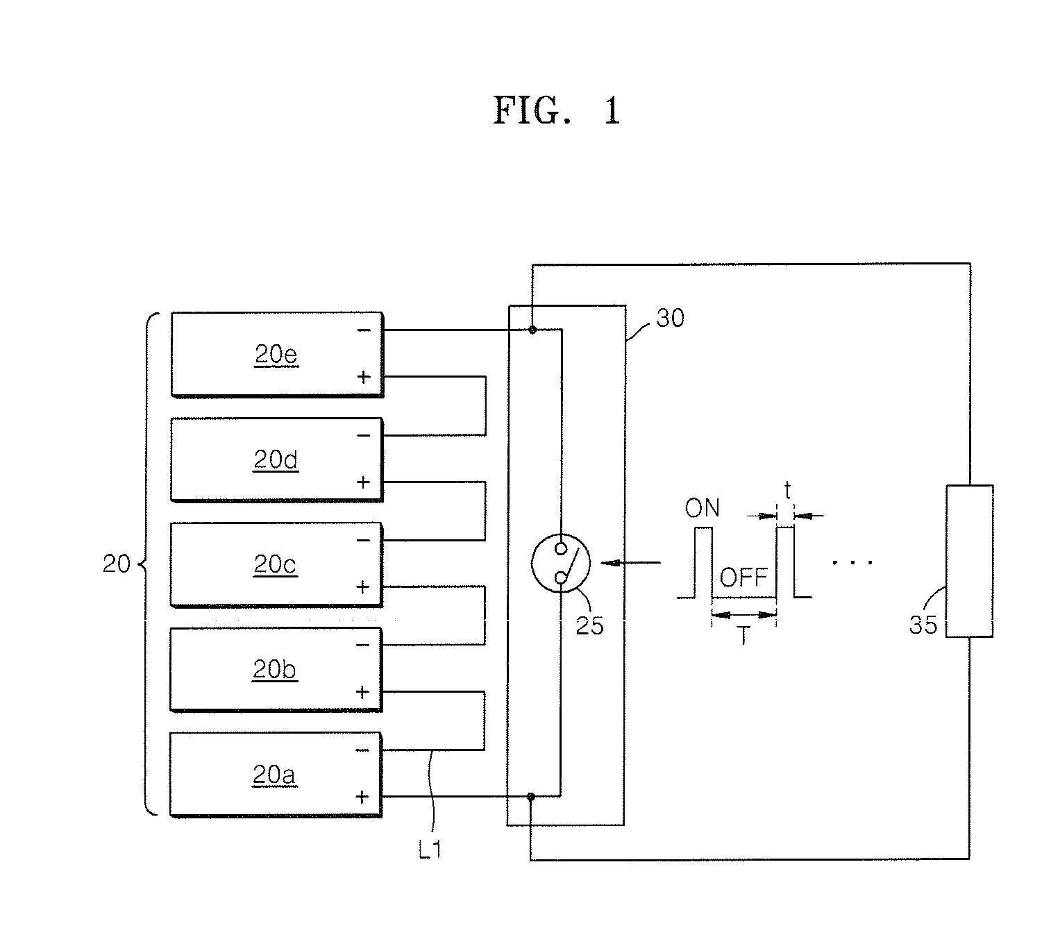
[0045]FIG. 1 is a circuit diagram illustrating a fuel cell system 100 and a method of operating a fuel cell 20 (fuel cell stack) using the same, according to an exemplary embodiment of the present invention.

[0046]Referring to FIG. 1, the fuel cell system 100 includes the fuel cell 20 (fuel cell stack) including first through fifth unit cells 20a-20e. The fuel cell 20 can be mono-polar. While the fuel cell 20 includes the five unit cells 20a-20e, in FIG. 1, the number of unit cells is not limited thereto. For example, the fuel cell 20 may include any suitable number ...


PUM


Abstract

A fuel cell system and a method of operating the same, the fuel cell system comprising: a fuel cell including at least one unit cell; an switch having first and second ends connected to different type electrodes of the fuel cell; and a circuit unit to detect whether a load is applied to the fuel cell, to control the operation of the switch according to the detection, cycle the switch open and closed to short circuit the fuel cell, in order to prevent the fuel cell from overheating and to consume a residual fuel in the fuel cell. The fuel cell system may further include a converter, a secondary cell, a battery charger, and a switching unit between the load and the fuel cell.

Description

CROSS-REFERENCE TO RELATED APPLICATIONS[0001]This application claims the benefit of Korean Application Nos. 2006-77775, filed Aug. 17, 2006 and 2007-49943, filed May 22, 2007, in the Korean Intellectual Property Office, the disclosure of which is incorporated herein by reference.BACKGROUND OF THE INVENTION[0002]1. Field of the Invention[0003]Aspects of the present invention relate to a power supplying device, and more particularly, to a fuel cell system and a method of operating the same.[0004]2. Description of the Related Art[0005]There are many types of fuel cells. Fuel cells can be divided into direct methanol fuel cells (DMFCs), which directly use methanol, and proton exchange membrane fuel cells (PEMFCs).[0006]A DMFC produces power in a process in which electrons and hydrogen ions, generated at an anode of a membrane electrode assembly (MEA), are moved to a cathode of the MEA and react with oxygen. The electrons and hydrogen ions are generated by reaction of methanol supplied f...

Claims


Application Information

Patent Timeline
IPC IPC(8): H01M8/04H01M10/44H02J7/00
CPCH01M8/04007Y02B90/18H01M8/04194H01M8/04216H01M8/04223H01M8/04365H01M8/04552H01M8/04559H01M8/04619H01M8/04731H01M8/04798H01M8/04955H01M8/1011H01M10/44H01M16/006H01M2250/30Y02E60/50H01M8/04186Y02B90/10Y02E60/10H01M8/04303H01M8/04228
Inventor LEE, JAE-YONGCHO, HYE-JUNGKIM, YOUNG-JAEHU, LEIJOUNG, YOUNG-SOO
Owner SAMSUNG SDI CO LTD
Why Eureka
Try Eureka