
Fuel cell stack

Inactive Publication Date: 2008-02-21
HYUNDAI MOTOR CO LTD
View PDF4 Cites 19 Cited by
  • Summary
  • Abstract
  • Description
  • Claims
  • Application Information

AI Technical Summary

Benefits of technology

[0013]The present invention has been made in an effort to provide a fuel cell stack having advantages of minimizing performance deviation due to temperature variations among cells which is generated while operating a fuel cell stack at a low temperature below 0 degrees, thereby improving a stability of a fuel cell.

Problems solved by technology

In particular, in the case that an external temperature drops below 0 degrees so that a temperature of a fuel cell stack becomes lower than the freezing point of water, i.e., in the winter season, the activity of the electrode deteriorates and the conductivity also deteriorates because of the freezing of water delivering hydrogen in the electrolyte membrane.
In the case that voltages are non uniform, a greater amount of current cannot be obtained because of a possibility of an inverse voltage in a cell with a low voltage.
Accordingly, since voltages of other cells become high, a greater amount of heat cannot be generated.
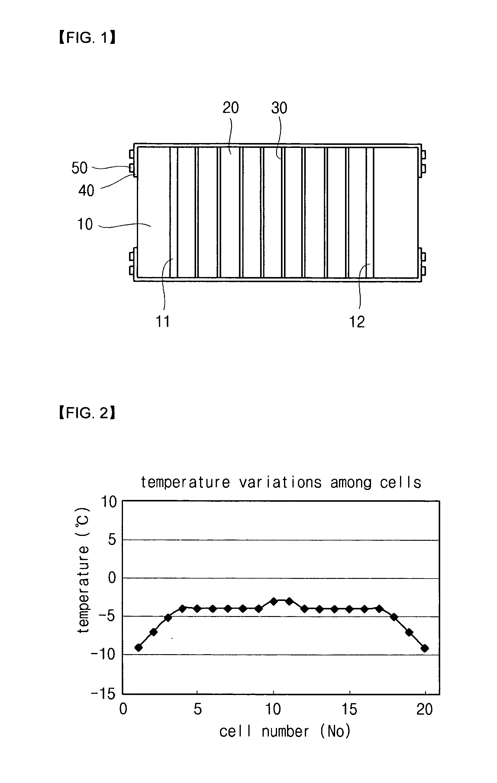
Accordingly, temperature variation occurs as shown in FIG. 2, and such a temperature variation causes performance of outside cells to be poorer than those cells positioned in the middle, so that a great amount of current cannot be obtained.
That is, there is a problem in that an overall amount of heat is decreased so that a time for increasing a temperature of the fuel cell stack to 0 degrees during a cold start is retarded.
However, such an insulator should be sufficiently thick for sufficient insulation, so that there is a drawback that the thickness of a fuel cell stack significantly increases.
In addition, since the insulator deprives a portion of heat, a problem of a performance deviation due to temperature variations among cells cannot be solved.
This creates a drawback in that a system for control has increased completely.

Method used


Image

  • Fuel cell stack
  • Fuel cell stack
  • Fuel cell stack

Examples


Embodiment Construction

[0031]An exemplary embodiment of the present invention will hereinafter be described in detail with reference to the accompanying drawings.

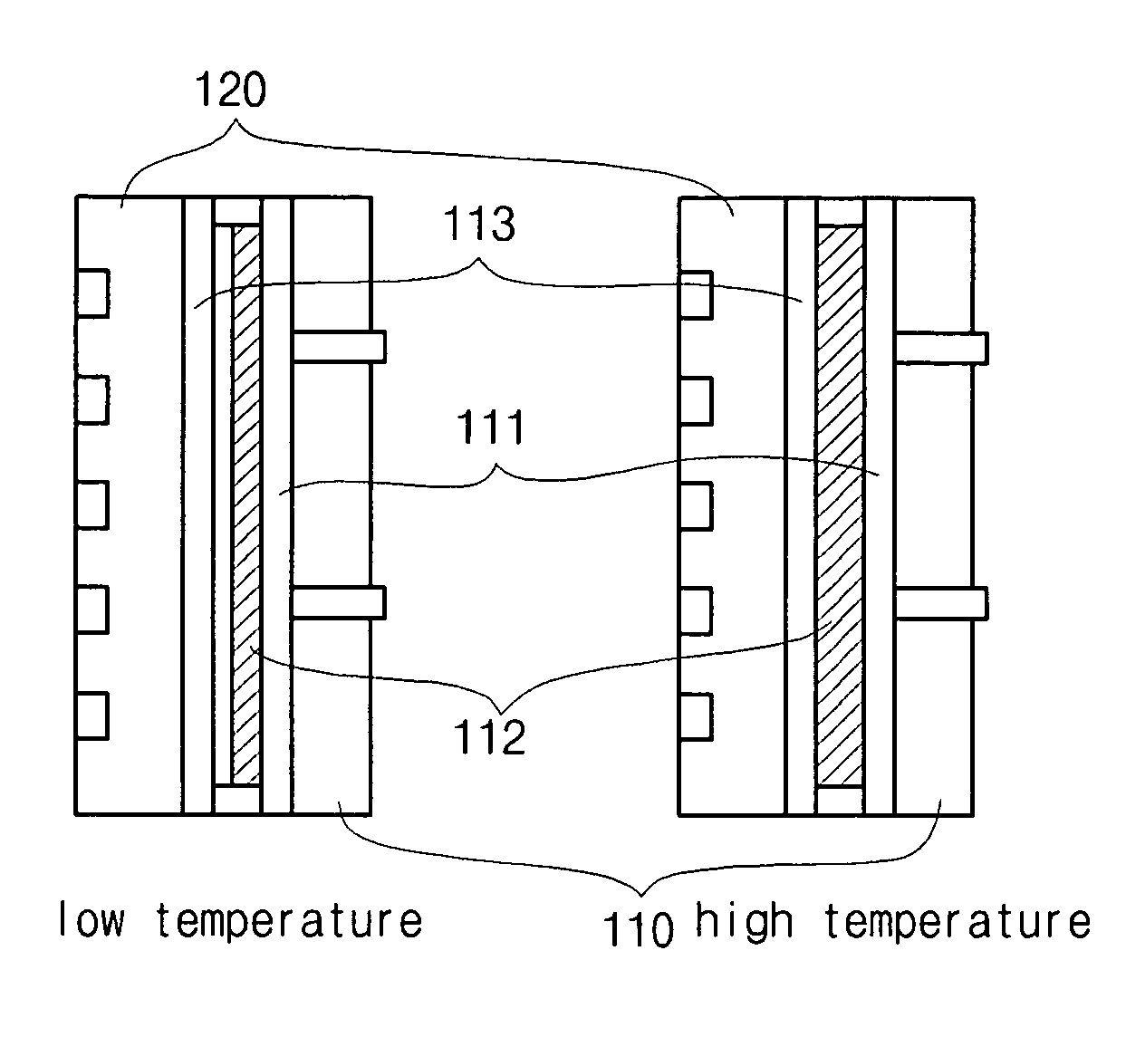
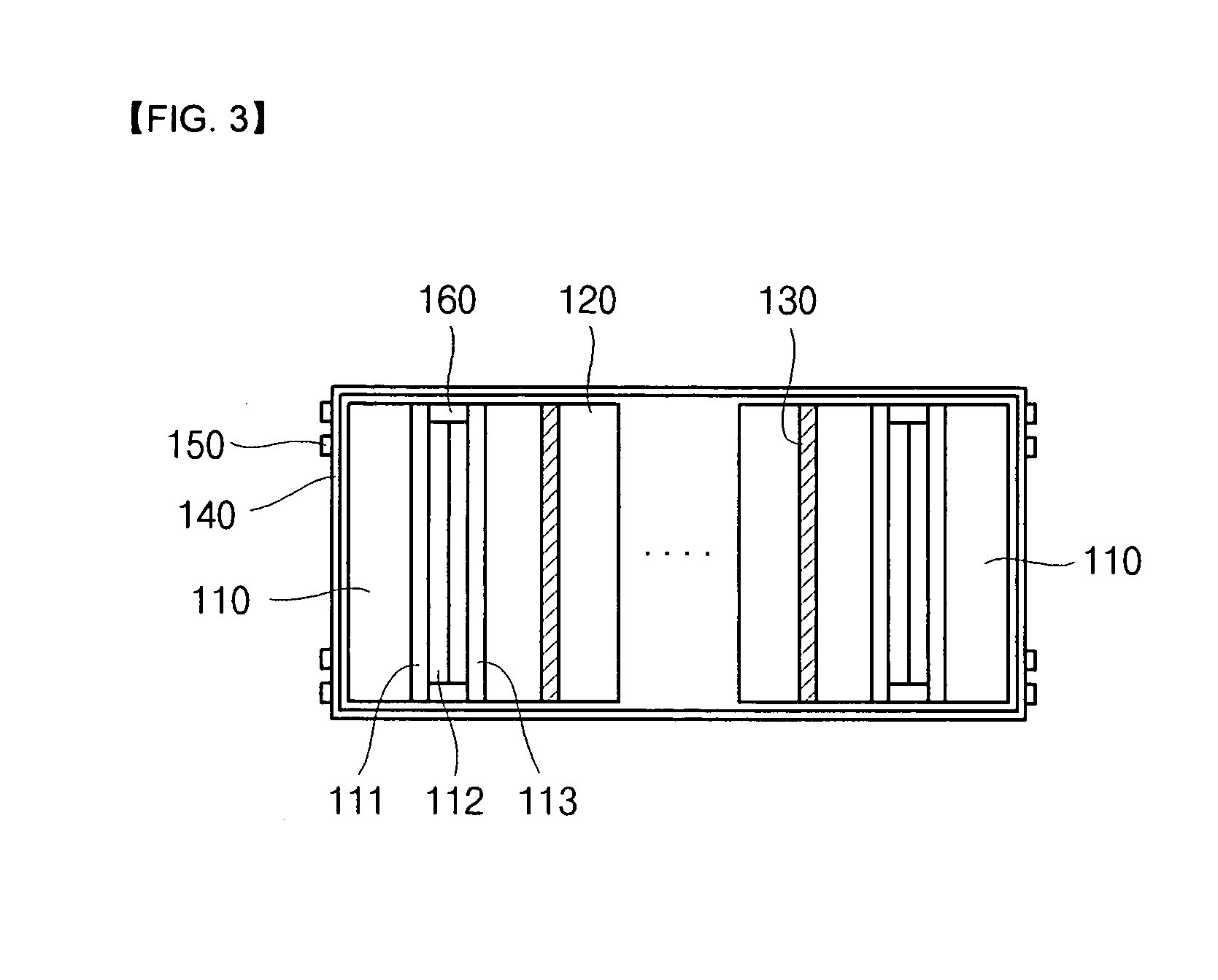
[0032]FIG. 3 is a drawing showing a structure of a fuel cell stack according to a first exemplary embodiment of the present invention, and FIG. 4 is a drawing showing a change in a current collector at a low temperature and at a high temperature.

[0033]Referring to FIG. 3 and FIG. 4, a fuel cell stack according to a first exemplary embodiment of the present invention includes: two end plates 110 arranged to be opposite to each other with a predetermined interval therebetween, first current collectors 111 respectively contacting insides of the end plates 110, second current collectors 112 respectively contacting insides of the first current collectors 111, third current collectors 113 selectively contacting the second current collector 112 depending on conditions, separators 120 respectively contacting insides of the third current collectors 113, a...


PUM


Abstract

The fuel cell stack includes: two end plates arranged to be opposite to each other with a predetermined interval therebetween; first current collectors respectively contacting insides of the end plates; second current collectors respectively contacting the first current collectors and having a coefficient of thermal expansion greater than that of the first current collectors; third current collectors selectively contacting the second current collectors depending on a surrounding temperature; separators respectively contacting an inside of the third current collectors; a membrane electrode assembly contacting the separators and disposed alternately with the separators so as to form a stack in which a plurality of cells are piled up; a connecting device encompassing the two end plates and elements arranged between the two end plates; and a bolt fixing the connecting device.

Description

CROSS-REFERENCE TO RELATED APPLICATION[0001]This application claims priority to and the benefit of Korean Patent Application No. 10-2006-0077284 filed in the Korean Intellectual Property Office on Aug. 16, 2006, the entire contents of which are incorporated herein by reference.FIELD[0002]The present invention relates to a fuel cell stack, and more particularly to a fuel cell stack having that enhances the stability during cold start using resistivity of double current collectors having different coefficients of thermal expansion.BACKGROUND[0003]Generally, a polymer electrolyte fuel cell has a greater efficiency than other types of fuel cells, and has a greater current density and output density. In addition, a polymer electrolyte fuel cell not only has a shorter start time but also has a faster response to changes in load. In particular, since a polymer membrane is used as the electrolyte, the polymer electrolyte fuel cell does not need suffer from corrosion. The electrolyte is also...

Claims


Application Information

Patent Timeline
IPC IPC(8): H01M8/24H01M8/10
CPCH01M8/0297H01M8/04052H01M8/04067Y02E60/50H01M8/2465H01M8/248H01M2008/1095H01M8/2415H01M8/241H01M8/24H01M8/02H01M8/2418
Inventor KO, JAE JUNLEE, JONG HYUNOH, SEUNG CHANYOON, JONG JIN
Owner HYUNDAI MOTOR CO LTD
Learn More