Method for compensating star motion induced error in a stellar inertial attitude determination system

a technology of inertial attitude determination and star motion, applied in the direction of vehicle position/course/altitude control, process and machine control, instruments, etc., to achieve the effect of improving the accuracy of attitude determination

Active Publication Date: 2008-02-21
THE BOEING CO
View PDF13 Cites 56 Cited by
  • Summary
  • Abstract
  • Description
  • Claims
  • Application Information

AI Technical Summary

Benefits of technology

[0009] The present invention describes a novel method to compute the predicted star positions by integrating the star motion during the star integration time period. Since the reported star positions represent the integration of the true star motion within the integration time period, the computed star...

Problems solved by technology

Hence, for spacecraft subject to agile motion, the prior art produces star residuals, which contain errors due t...

Method used


Image

  • Method for compensating star motion induced error in a stellar inertial attitude determination system
  • Method for compensating star motion induced error in a stellar inertial attitude determination system
  • Method for compensating star motion induced error in a stellar inertial attitude determination system

Examples


Embodiment Construction

[0021] In the following description, reference is made to the accompanying drawings which form a part hereof, and which is shown, by way of illustration, several embodiments of the present invention. It is understood that other embodiments may be utilized and structural changes may be made without departing from the scope of the present invention. While the present invention is described with respect to a satellite, various types of vehicles may benefit from the use of the present invention. Various types of vehicles may have uses for the present invention and include but are not limited to aircraft, ships, stratospheric platforms, missile guidance systems, gimbaled telescopes, and space station applications. Similarly, the invention can be applied to optical sensors other than star sensors, particularly to centroiding optical sensors.

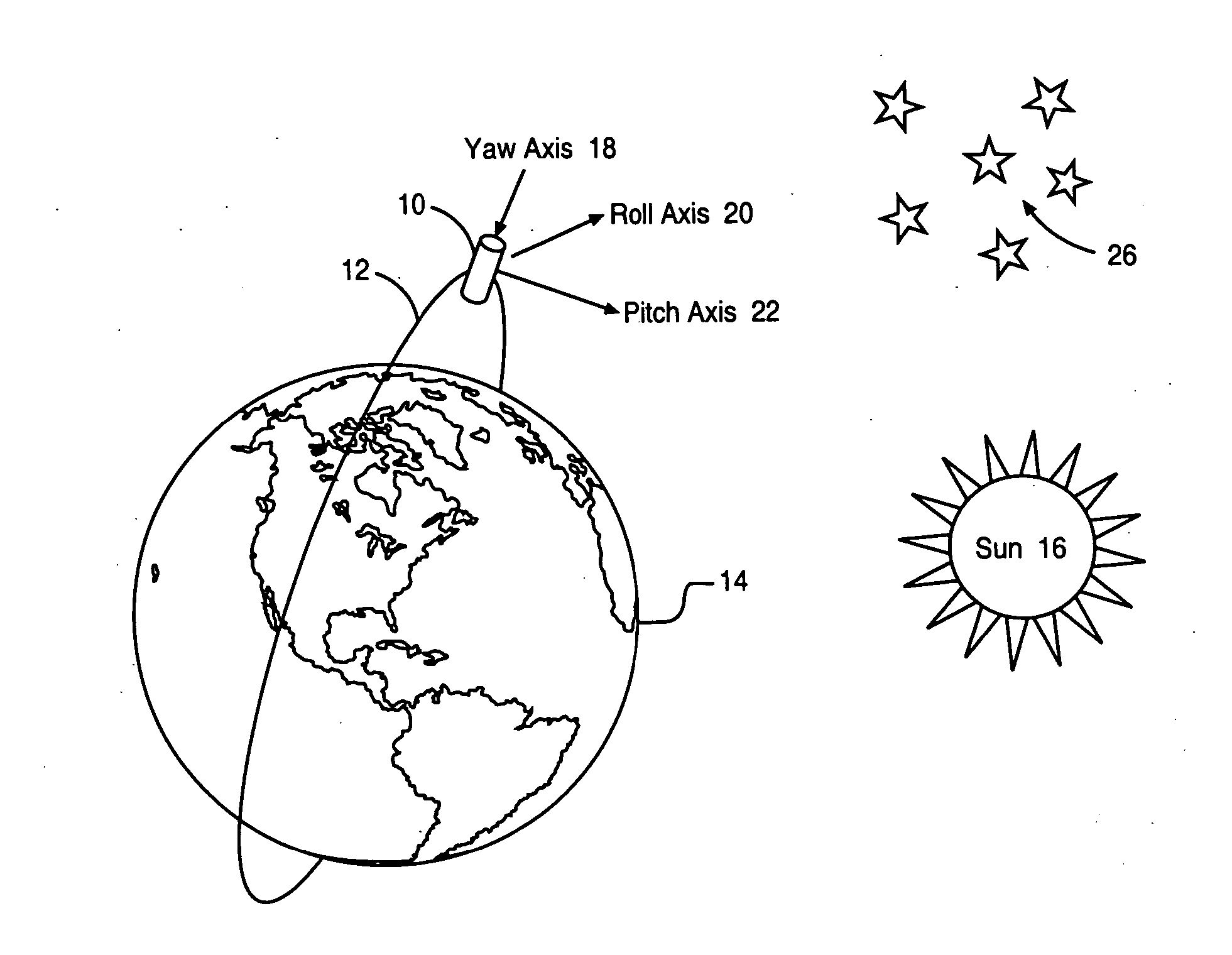
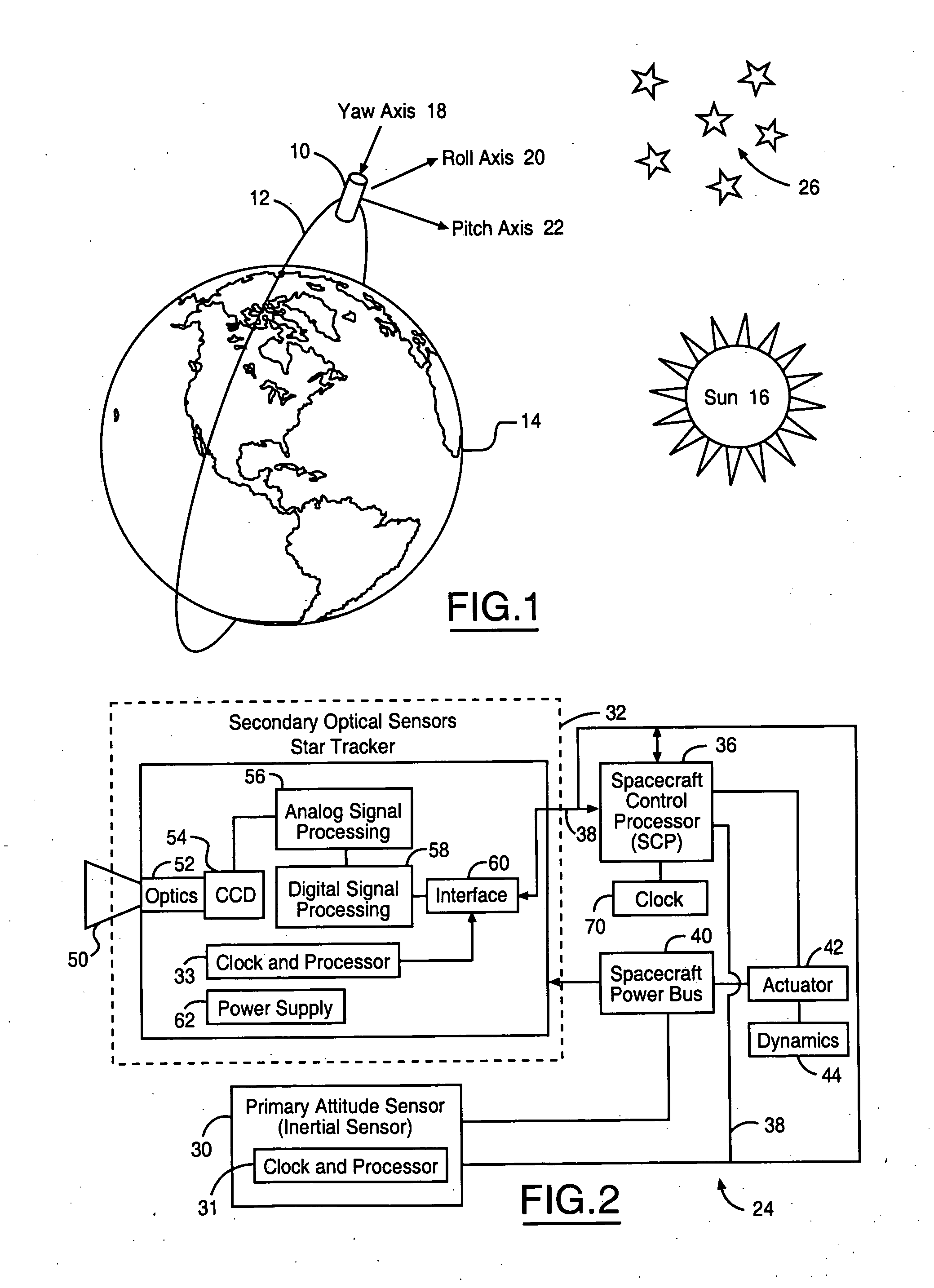
[0022] Referring to FIG. 1, a vehicle, such as a satellite 10 is shown in orbit 12 around the earth 14. Three mutually orthogonal axes, labeled yaw a...


PUM


Abstract

A method for controlling an actuator of a vehicle comprises providing a dynamic condition sensor generating a vehicle movement signal and a position sensor for generating a reported position. A processor is coupled to the inertial sensor and the position sensor and comprises an estimator, a position measurement predictor having a filter, a comparator and a control shaping block, said estimator generating a vehicle position based upon the dynamic condition sensor, said position measurement predictor generating an estimated position measurement in response to the reported vehicle position and a matched frequency response to the movement signal, said control shaping block generating an actuator control signal in response to a comparison of the estimated position measurement and the reported vehicle position.

Description

FEDERAL RESEARCH STATEMENT [0001] This invention was made with Government support. The Government has certain rights in this invention.TECHNICAL FIELD [0002] The present invention relates to systems and methods for the guidance and control of vehicles, and in particular to a system and method for mitigating the effect of star motion on optical sensor data. BACKGROUND ART [0003] Satellites and other vehicles are in widespread use for various purposes including scientific research and communications. Many scientific and communications missions, however, cannot be accurately fulfilled without consistently monitoring and controlling the 3-axis attitude and angular velocity of the vehicle. Attitude may be described as the vehicle orientation with respect to some frame, for example, the Earth-Centered Inertial (ECI) frame. In many applications, the vehicle must be oriented to transmit signals in particular directions or to receive signals from specifically located sources. Furthermore, in...

Claims


Application Information

Patent Timeline
IPC IPC(8): B64G1/36
CPCG05D1/0883B64G1/36B64G1/244
Inventor FOWELL, RICHARD A.LI, RONGSHENGWU, YEONG-WEI A.
Owner THE BOEING CO
Why Eureka
Try Eureka