Device and method for sequentially cold working and reaming a hole

a technology of sequential cold working and reaming holes, which is applied in the direction of handling devices, forging/pressing/hammering apparatuses, and tools for shaping tools. it can solve the problems of time-consuming and skilled technicians, and achieve the effect of enlarge the hol

Active Publication Date: 2008-02-28
NORTHROP GRUMMAN SYST CORP
View PDF8 Cites 13 Cited by
  • Summary
  • Abstract
  • Description
  • Claims
  • Application Information

AI Technical Summary

Benefits of technology

[0007]In the above embodiment, the reamer section is aligned with the tip of the forward end portion. Such that the reamer section is the first mechanism engaging the hole to enlarge the hole, and the enlarged hole is then cold worked by the burnisher section adjacent to the reamer section. In an alternate embodiment, the burnisher section is aligned with the tip of the forward end of the elongate body to operate as the first mechanism to engage the hole. Therefore, the material is subject to the cold work process prior to the reaming application applied thereto. In either way, an accurately sized diameter of the hole with a round cross section that is not distorted or oval as can be the case with twist drills can be achieved.
[0008]In yet another embodiment, the reamer mechanism and the cold work mechanism are combined with the drill member, such that a hole can be drilled, reamed, and cold worked with a single tool in a single step. In this embodiment, the tool includes an elongate body, preferably a cylindrical body, having a proximal end and a distal end. The...

Problems solved by technology

The process as shown in FIG. 1A to FIG. 1D is time ...

Method used


Image

  • Device and method for sequentially cold working and reaming a hole
  • Device and method for sequentially cold working and reaming a hole
  • Device and method for sequentially cold working and reaming a hole

Examples


Embodiment Construction

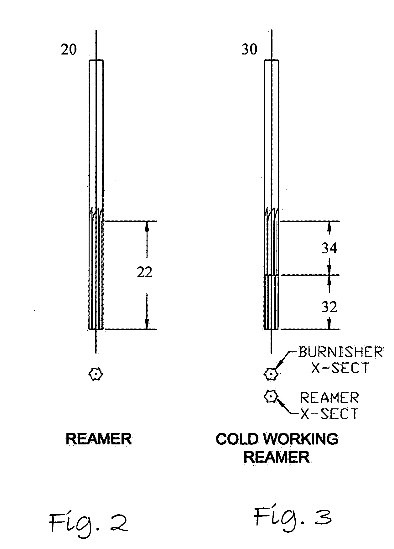
[0016]FIG. 2 illustrates the side view and cross view of a typical reamer. As shown, the reamer includes a cylindrical body 20 and a set of parallel straight cutting edges 22 formed at a forward end of the cylindrical body 20. As shown in the cross sectional view in FIG. 2, each of the cutting edges 22 is ground at a slight angle with a slight undercut below the cutting edge. As desired, the reamer must combine both hardness in the cutting edge for long life and toughness so that tool does not fail under the normal force of use. For each reaming process applied to a hole, only a small amount of material is expected to be removed by the reamer to ensure a long life of the reamer and a superior finish to the hole. Although FIG. 2 illustrates the parallel straight cutting edges 22 only, it would be appreciated that different arrangement, for example, helical arranged cutting edges 22 may also be formed at the forward end of the cylindrical body 20 to achieve specific reaming effect.

[00...


PUM

PropertyMeasurementUnit
Diameteraaaaaaaaaa
Areaaaaaaaaaaa
Circumferenceaaaaaaaaaa

Abstract

A device and a method are provided to allow a user to ream a hole to an accurate final diameter as desired, and at the same time, to cold work the hole to induce a beneficial residual stress that will enhance the life of the component by retarding the onset and growth of fatigue cracks in the hole. The basic design of the device has an elongated body having a forward end portion to extend through a hole to be reamed and cold worked, a reamer section formed on the circumference of the forward end portion to enlarge the hole, and a burnishing section formed on the circumference of the elongated body adjacent to the reamer. The burnishing section is operative to upset the material around the hole, so as to result in a residual stress beneficial to the hole. The reamer section is in the form of a plurality of cutting edges extending from a tip of the elongated body, while the burnishing section is also in the form of a plurality of cutting edges adjacent to the reamer section along the elongate body. The cutting edges of the reamer sections are parallel straight cutting edges or helical cutting edges. The cutting edges of the burnishing section are configured with an orientation opposite to that of the cutting edges of the reaming section. Therefore, when the cutting edges of the burnishing section are configured with the same profile as the cutting edges of the reamer section, the burnishing section is in the form of a backward reamer section.

Description

CROSS-REFERENCE TO RELATED APPLICATIONS[0001]Not ApplicableSTATEMENT RE: FEDERALLY SPONSORED RESEARCH / DEVELOPMENT[0002]Not ApplicableBACKGROUND[0003]The present invention relates in general to a device and a method to ream a hole to an accurate final diameter and cold work the hole to induce a beneficial residual stress that will enhance the life of the component by retarding the onset and growth of fatigue cracks in the hole.[0004]When a hole is drilled or bored through a metal and enlarged by a reamer, cold work is often applied to the hole to enhance its fatigue life. FIGS. 1A to 1D illustrate the steps required for a conventional cold work after a hole is initially drilled. As shown in FIG. 1A, after a hole 12 is drilled through a material 10, a tapered mandrel 14 pre-fitted with a lubricated split sleeve 16 is used to insert through the hole 12 in the material such as aluminum, steel, titanium or other metals. The function of the disposable split sleeve 16 is to reduce mandrel ...

Claims


Application Information

Patent Timeline
IPC IPC(8): B21D37/01
CPCB23B51/009B23D77/00B23D2277/14Y10T29/47B24B39/02Y10T408/34B23P9/025B23B51/08
Inventor CHRIST, ROBERT J.NARDIELLO, JERRELL A.PAPAZIAN, JOHN M.MADSEN, JOHN STEVEN
Owner NORTHROP GRUMMAN SYST CORP
Why Eureka
Try Eureka