Ultrasonic stress measuring apparatus

a technology of ultrasonic stress and measuring apparatus, which is applied in the direction of instruments, force/torque/work measurement, and specific gravity measurement, etc., can solve the problems of inability to apply data, inability to obtain a signal sufficient to accurately and difficulty in using it to measure a residual stress on the job si

Inactive Publication Date: 2008-02-28
KK TOSHIBA
View PDF12 Cites 21 Cited by
  • Summary
  • Abstract
  • Description
  • Claims
  • Application Information

AI Technical Summary

Benefits of technology

[0040] According to the present invention, the sound velocity data of the respective SAW are calculated by causing both the longitudinal and shear wave probes to carry out a transmission / reception operation to the same to-be-measured portion of a material, and, in particular, causing the shear wave probe to carry out the transmission / reception operation at each of a plurality of times of rotation, it is possible to separate only texture induced anisotropy from the material in which both the texture induced anisotropy and residual stress induced anisotropy mixedly exist. Accordingly, it is possible to provide an ultrasonic stress measuring apparatus capable of measuring the residual stress of a material with pinpoint accuracy.

Problems solved by technology

However, since the strain gauge requires to cut and to take out a part of a to-be-measured structure as a test piece, it is difficult to use it to measure a residual stress in a job site.
However, since the X-ray stress measuring apparatus uses an X-ray, background noise is increased in a radioactive environment such as in the nuclear power plant, and thus the X-ray stress measuring apparatus has a drawback in that a signal sufficient to measure a residual stress accurately cannot be obtained.
However, the constant of acoustic anisotropy defined by the method relates to the shear wave traveling in a material and does not relate to the texture induced anisotropy necessary to measure a surface stress.
In these methods, since it is a premise that the data of the material before it is used exist, they cannot be applied when the data does not exist.
However, the method discloses nothing as to the texture induced anisotropy of an SAW likewise.
However, since both texture induced anisotropy and residual stress induced anisotropy are ordinarily mixed, there is not a technology for separately determining only the texture induced anisotropy.
Accordingly, it cannot conventionally measure the residual stress of a material with accuracy higher than a predetermined level.

Method used


Image

  • Ultrasonic stress measuring apparatus
  • Ultrasonic stress measuring apparatus
  • Ultrasonic stress measuring apparatus

Examples


Embodiment Construction

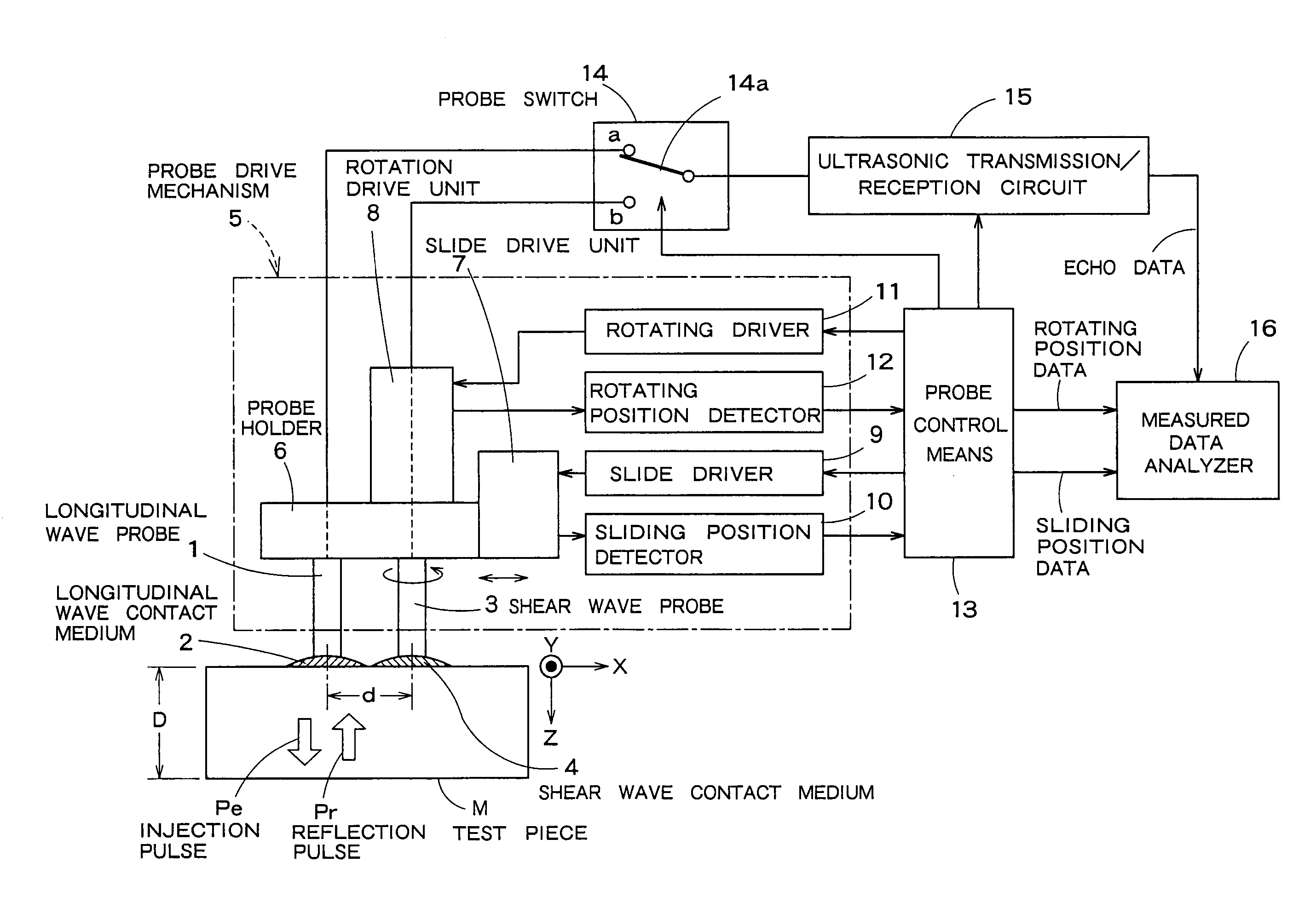
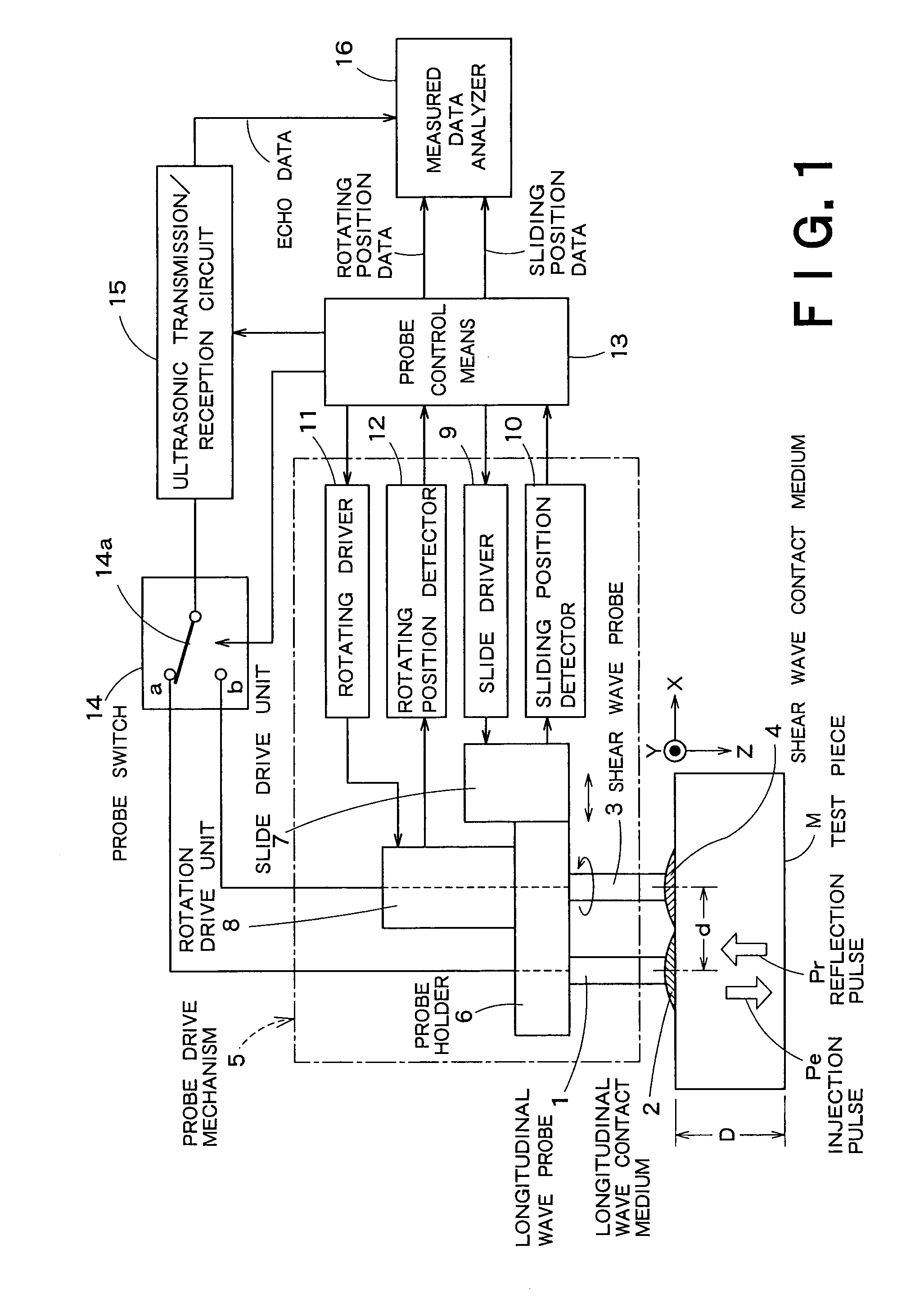
[0046]FIG. 1 is an arrangement view of an ultrasonic stress measuring apparatus of an embodiment according to the present invention. An XY coordinate plane is set on a flat surface of a test piece M (stress measurement material) having a thickness D, and the XY coordinate plane has an X-axis and a Y-axis vertical to the X-axis, and a Z-axis is set to the XY coordinate plane in a vertical direction.

[0047] One end of a longitudinal wave probe 1 is disposed on a surface of the test piece M through a longitudinal wave contact medium 2, and one end of a shear wave probe 3 is disposed at a position apart from the longitudinal wave ultrasonic probe 1 a distance d through a shear wave contact medium 4.

[0048] The longitudinal wave probe 1 and the shear wave probe 3 are driven by a probe drive mechanism 5. That is, the other ends of the longitudinal wave probe 1 and the shear wave probe 3 are supported by a probe holder 6, and a slide drive unit 7 and a rotation drive unit 8 are attached to...


PUM


Abstract

After a probe control means causes a longitudinal wave probe to carry out transmission and reception, it slides a shear wave probe to the same position. The probe control means rotates the shear wave probe at each predetermined angle and rotates it 180° while causing it to carry out the transmission and the reception at each rotating position. A measured data analyzer 16 calculates the constant of texture induced anisotropy in a test piece from echo data when both the probes carry out the transmission and the reception. With this arrangement, it is possible to measure the residual stress of a material, in which both texture induced anisotropy and residual stress induced anisotropy mixedly exist with pinpoint accuracy by separating only the texture induced anisotropy from the material.

Description

BACKGROUND OF THE INVENTION [0001] 1. Field of the Invention [0002] The present invention relates to an ultrasonic stress measuring apparatus used to a technology for diagnosing material deterioration and the like. [0003] 2. Related Art [0004] The role of a material deterioration diagnosis apparatus has become important as a planning maintenance technology of a nuclear power plant. This is because it is increasingly required to measure a residual stress, which is one of the reasons for causing a fatigue crack and a stress corrosion crack of the structures and the pipings in a reactor and to improve a stress as a countermeasure for preventing them. [0005] A strain gauge is a simplest device as a residual stress measuring means. However, since the strain gauge requires to cut and to take out a part of a to-be-measured structure as a test piece, it is difficult to use it to measure a residual stress in a job site. [0006] Accordingly, it is considered to use an X-ray stress measuring ap...

Claims


Application Information

Patent Timeline
Patent Type & Authority Applications(United States)
IPC IPC(8): G01H5/00
CPCG01L5/0047G01N29/043G01N29/07G01N2291/0422G01N2291/0258G01N2291/02827G01N2291/0421G01N29/265
Inventor SATO, MICHIOWATANABE, KAZUMIASANO, MASAYUKISUMIYA, RIEKIKUCHI, MASAAKI
Owner KK TOSHIBA
Why Eureka
Try Eureka