Apparatus, circuitry, signals and methods for cleaning and processing with sound

a technology of circuitry and signals, applied in the direction of cleaning process and apparatus, chemistry apparatus and process, cleaning using liquids, etc., can solve the problems of modern jet engine turbine blades that can fracture, large features of semiconductor wafers, and small features, so as to prevent low frequency resonance and eliminate possible resonances

Inactive Publication Date: 2008-02-28
PUSKAS WILLIAM L
View PDF97 Cites 14 Cited by
  • Summary
  • Abstract
  • Description
  • Claims
  • Application Information

AI Technical Summary

Benefits of technology

[0039]The invention further provides a system for delivering ultrasound to liquid. This system includes one or more ultrasound transducers, each having an operating frequency within an ultrasound bandwidth. An amplitude modulated ultrasound generator drives the transducers at frequencies within the bandwidth. A generator subsystem also changes the modulation frequency of the AM, continually, so as to produce ultrasound within the liquid to prevent low frequency resonances at the AM frequency.
[0040]Preferably, the subsystem sweeps the AM frequency at a sweep rate between about 1 hz and 100 hz. For extremely sensitive parts and / or tank chemistries, the invention can further sweep the AM sweep rate as a function of time so as to eliminate possible resonances which might be generated by the AM sweep rate frequency. This sweeping of the AM sweep rate occurs for a range of AM sweep frequencies generally defined by 10-40% of the optimum AM sweep rate. For example, if the optimum AM sweep rate is 150 hz, then one aspect of the invention changes the AM sweep rate through a range of about 130 hz and 170 hz.

Problems solved by technology

By way of example, one delicate part is a semiconductor wafer which has extremely small features and which is easily damaged by cavitation implosion.
Another delicate part is a modern jet engine turbine blade which can fracture if excited into resonant vibration.

Method used


Image

  • Apparatus, circuitry, signals and methods for cleaning and processing with sound
  • Apparatus, circuitry, signals and methods for cleaning and processing with sound
  • Apparatus, circuitry, signals and methods for cleaning and processing with sound

Examples


Embodiment Construction

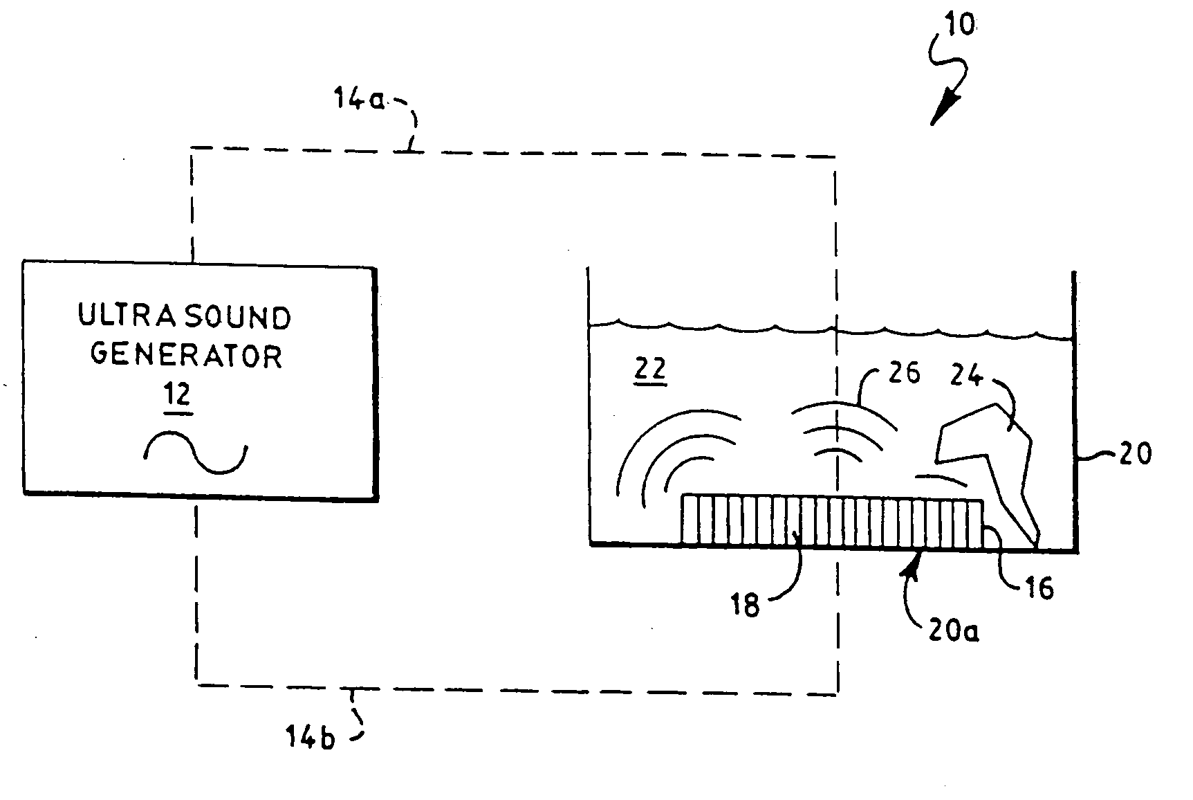
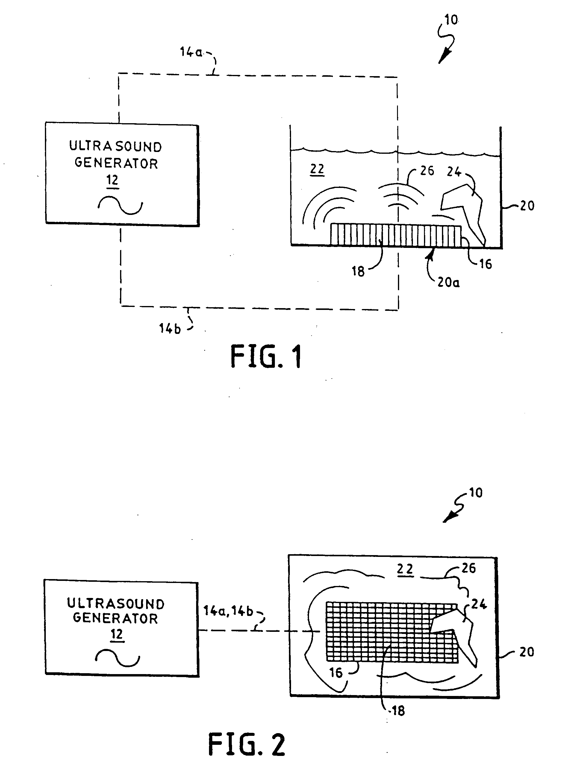
[0234]FIGS. 1 and 2 show schematic side and top views, respectively, of an ultrasound processing system 10 constructed according to the invention. An ultrasound generator 12 electrically connects, via electrical paths 14a, 14b, to an ultrasound transducer 16 to drive the transducer 16 at ultrasound frequencies above about 18 khz, and usually between 40 khz and 350 khz. Though not required, the transducer 16 is shown in FIG. 1 as an array of transducer elements 18. Typically, such elements 18 are made from ceramic, piezoelectric, or magnetostrictive materials which expand and contract with applied voltages or current to create ultrasound. The transducer 16 is mounted to the bottom, to the sides, or within the ultrasound treatment tank 20 through conventional methods, such as known to those skilled in the art and as described above. A liquid 22 fills the tank to a level sufficient to cover the delicate part 24 to be processed and / or cleaned. In operation, the generator 12 drives the t...


PUM


Abstract

The invention utilizes a multiple frequency ultrasound generator driving a multiple frequency harmonic transducer array to improve cleaning and processing effects while eliminating damage to parts being cleaned. An AC switch and circuitry to modify the output of an ultrasound generator in combination with techniques such as random AM and FM signals are used to produce ultrasound waves that have no single frequency components which eliminates exciting parts being cleaned into resonance. Generator signals that increase cavitation efficiency and that have successive time periods with predominately stable cavitation and predominantly transient cavitation further improve the performance of the cleaning or processing systems.

Description

RELATED APPLICATIONS[0001]The subject application is a divisional of U.S. patent application Ser. No. 10 / 855,135, filed on May 27, 2004, which is a continuation-in-part of commonly owned and co-pending U.S. patent applications Ser. Nos. 10 / 178,751 and 10 / 825,036, each of which is expressly incorporated herein by reference. Each of these applications has a history that is detailed below.[0002]History of U.S. patent application Ser. No. 10 / 178,751: U.S. patent application Ser. No. 10 / 178,751 filed Jun. 24, 2002, entitled “Apparatus, Circuitry and Methods for Cleaning and / or Processing with Sound Waves”, still pending, which is a continuation in part of four U.S. patent application Ser. Nos. 09 / 370,302, 09 / 609,036, 09 / 678,576 and 10 / 029,751 the history of each is described below.[0003]History of U.S. patent application Ser. No. 09 / 370,302: U.S. patent application Ser. No. 09 / 370,302 filed Aug. 9, 1999, entitled “Probe System for Ultrasonic Processing Tank”, still pending, which is a di...

Claims


Application Information

Patent Timeline
Patent Type & Authority Applications(United States)
IPC IPC(8): B08B3/12B08B3/00
CPCB08B3/12
Inventor PUSKAS, WILLIAM L.
Owner PUSKAS WILLIAM L
Why Eureka
Try Eureka