Thermoelectric device

a technology of thermoelectric devices and components, applied in the direction of electrical equipment, vehicle components, vehicle arrangements, etc., can solve the problem of reducing and achieve the effect of improving the volume of the semiconductor elements

Inactive Publication Date: 2008-02-28
GENTHERM INC
View PDF99 Cites 85 Cited by
  • Summary
  • Abstract
  • Description
  • Claims
  • Application Information

AI Technical Summary

Benefits of technology

[0011] In other embodiments, a thermoelectric device includes first and second substrates and a plurality of semiconductor elements comprising a center, the semiconductor elements disposed between the first and second substrates, the plurality of semiconductor elements comprising a first group of semiconductor elements having a first set of electrical properties and a second set of semiconductor elements having a second set of electrical properties. The thermoelectric device further includes a first set of electrical conductors disposed between the plurality of semiconductors and the first substrate and a second set of electrical conductors disposed between the plurality of semiconductors and the second substrates. In one embodiment, the semiconductor elements are arranged in series and a density of semiconductor elements is higher in a first portion of the thermoelectric device than in at least one other portion of the thermoelectric device.

Problems solved by technology

However, if the spacing between semiconductor elements is kept the same as in arrangements with square cross-sectional shapes, the semiconductor elements lose some of their volume (e.g., the “corners” of the square are cut off to make the cylinder).

Method used


Image

  • Thermoelectric device
  • Thermoelectric device
  • Thermoelectric device

Examples


Embodiment Construction

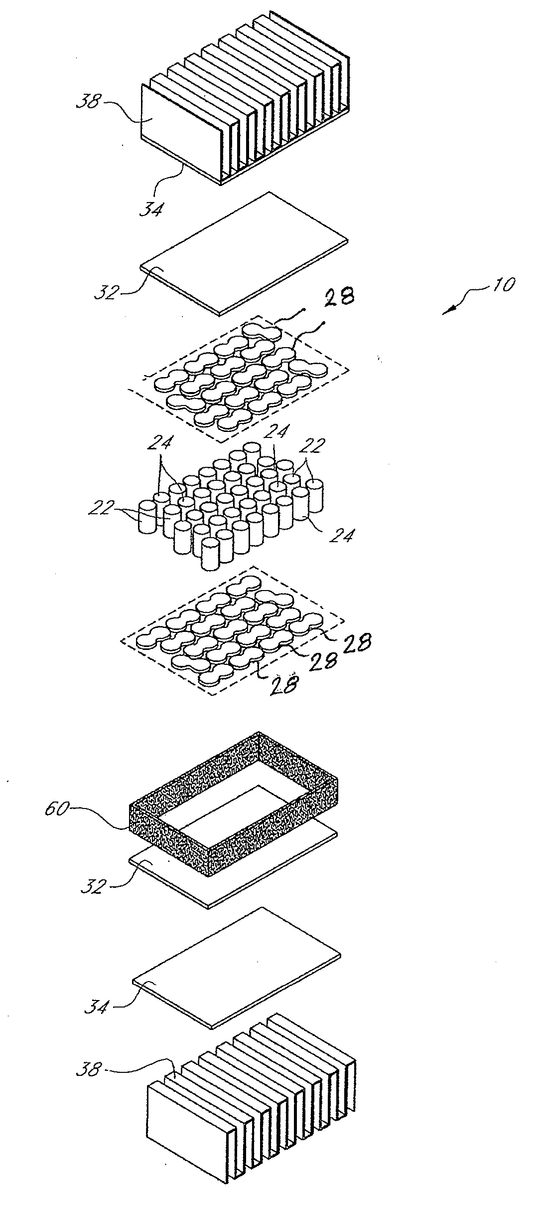
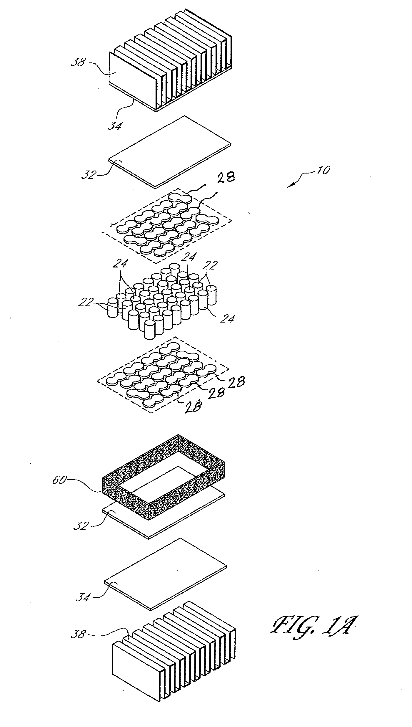
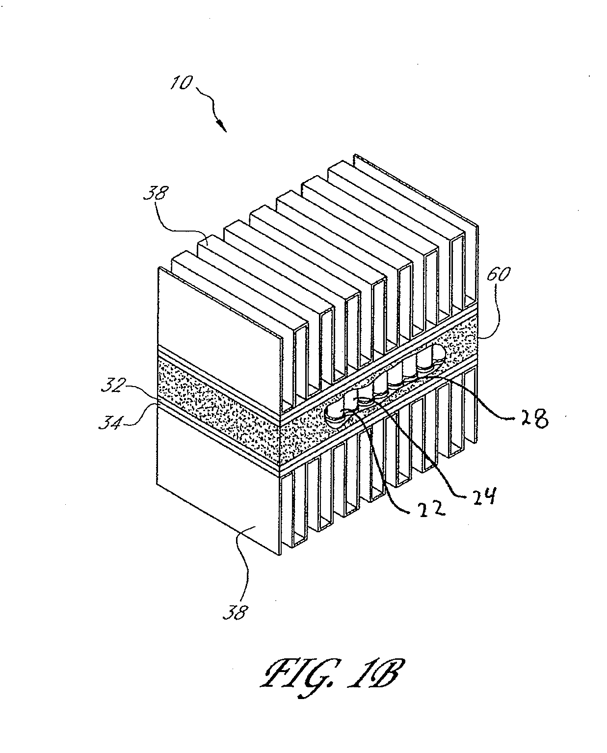
[0034] The thermoelectric devices and the various systems, apparatuses, methods and features associated with them are described in the context of a climate controlled seating assembly for an automobile or other vehicle because they have particular utility in this context. However, the devices, systems and methods described herein, as well as their various features, can be used in other contexts as well, such as, for example, but without limitation, for other climate controlled seating assemblies (e.g., beds, office chairs, theater seats, sofas, etc.), other climate control devices (e.g., climate controlled pet houses) and the like.

[0035] The various embodiments of thermoelectric devices disclosed and illustrated in this application include semiconductor elements that are arranged in a repeating hexagonal or other closely-packed pattern. Such arrangements can advantageously help reduce or minimize the space between adjacent semiconductor elements. Thus, such arrangements can help in...


PUM


Abstract

A thermoelectric device comprises a plurality of semiconductor elements comprising a first set of semiconductor elements and a second set of semiconductor elements, which include dissimilar electrical properties. The semiconductor elements are oriented in a substantially hexagonal array that includes rows in which semiconductor elements of the first and second sets of semiconductor elements alternate. The thermoelectric device also comprises a first set of electrical conductors and a second set of electrical conductors; each of the first set of electrical conductor being electrically coupled to the first end of a semiconductor element of the first set of semiconductor elements and the first end of a semiconductor element of the second set of semiconductor elements, each of the second set of electrical conductors are electrically coupled to the second end of a semiconductor element of the first set of semiconductor elements and the a second end of a semiconductor element of the second set of semiconductor elements such that the plurality of semiconductor elements are electrically coupled to each other in series.

Description

CROSS-REFERENCE TO RELATED APPLICATIONS [0001] This application claims the priority benefit under 35 U.S.C. § 119(e) of U.S. Provisional Application No. 60 / 821,376, filed Aug. 3, 2006, the entirety of which is hereby incorporated by reference herein.BACKGROUND OF THE INVENTION [0002] 1. Field of the Invention [0003] The present invention relates generally to thermoelectric devices and, more particularly, to a Peltier circuit. [0004] 2. Description of the Related Art [0005] A Peltier circuit is a thermoelectric device comprising two sides. When voltage is applied in one direction, one side creates heat while the other side absorbs heat. Switching polarity of the circuit creates the opposite effect. In a typical arrangement, a Peltier device comprises a closed circuit that includes dissimilar materials. As a DC voltage is applied to the closed circuit, a temperature change is produced at the junction of the dissimilar materials. Depending on the direction of the electrical current, he...

Claims


Application Information

Patent Timeline
Patent Type & Authority Applications(United States)
IPC IPC(8): H01L35/28H01L35/02
CPCB60N2/5635H01L35/32B60N2/5692B60N2/5657H10N10/17
Inventor LOFY, JOHN
Owner GENTHERM INC
Why Eureka
Try Eureka