Peel plate assembly for removing programmable transponders from a web

a technology of programmable transponders and webs, applied in the direction of burglar alarm mechanical actuation, instruments, etc., can solve the problems of increased number of programmable transponders being mis-programmed or misread as defective, less reliability of communication, and increased time-consuming and expensive problems, so as to avoid complications with the threading of the web and isolate communication.

Inactive Publication Date: 2008-02-28
WS PACKAGING GROUP
View PDF19 Cites 14 Cited by
  • Summary
  • Abstract
  • Description
  • Claims
  • Application Information

AI Technical Summary

Benefits of technology

[0009]The invention features a peel plate assembly of the type that can be incorporated into an applicator for selectively applying programmable transponders to articles. Preferably, the programmable transponders are embedded within label or tag structures that are arranged in a succession along a web. An interrogating device preferably includes an antenna that is protected inside a plate body of the peel plate assembly across which the web is guided. The antenna can be shielded behind a web guide of the peel plate assembly for limiting communications with the antenna to one transponder at a time. A peel blade of the peel plate assembly is moveable into and out of positions interrupting the web guide for selectively removing embedded transponders from the web. An actuator for the peel blade is responsive to the results of the interrogation so that only successfully polled transponders are removed from the web. Mounting the antenna within the peel plate and behind a web guide protects the antenna from damage, avoids complications with the threading of the web, and isolates communications between the antenna and individually embedded transponders.

Problems solved by technology

The programmable transponders are generally programmed or pre-programmed and read before the programmable transponders are applied to articles because article-to-article variations make subsequent communications less reliable.
At high processing speeds, such less reliable communications can lead to an increased number of programmable transponders being mis-programmed or misread as defective.
Defective transponders applied to articles can require scrapping packaging together with the defective transponders, which is more time consuming and expensive than detecting transponder defects earlier and with more reliability.
However, many difficulties have been encountered including threading the webs past the antenna, damaging antenna that track too close to the web, encountering interference from nearby transponders, accidentally re-encoding or re-reading the nearby transponders, and limiting locations of the transponders on the webs.

Method used


Image

  • Peel plate assembly for removing programmable transponders from a web
  • Peel plate assembly for removing programmable transponders from a web
  • Peel plate assembly for removing programmable transponders from a web

Examples


Embodiment Construction

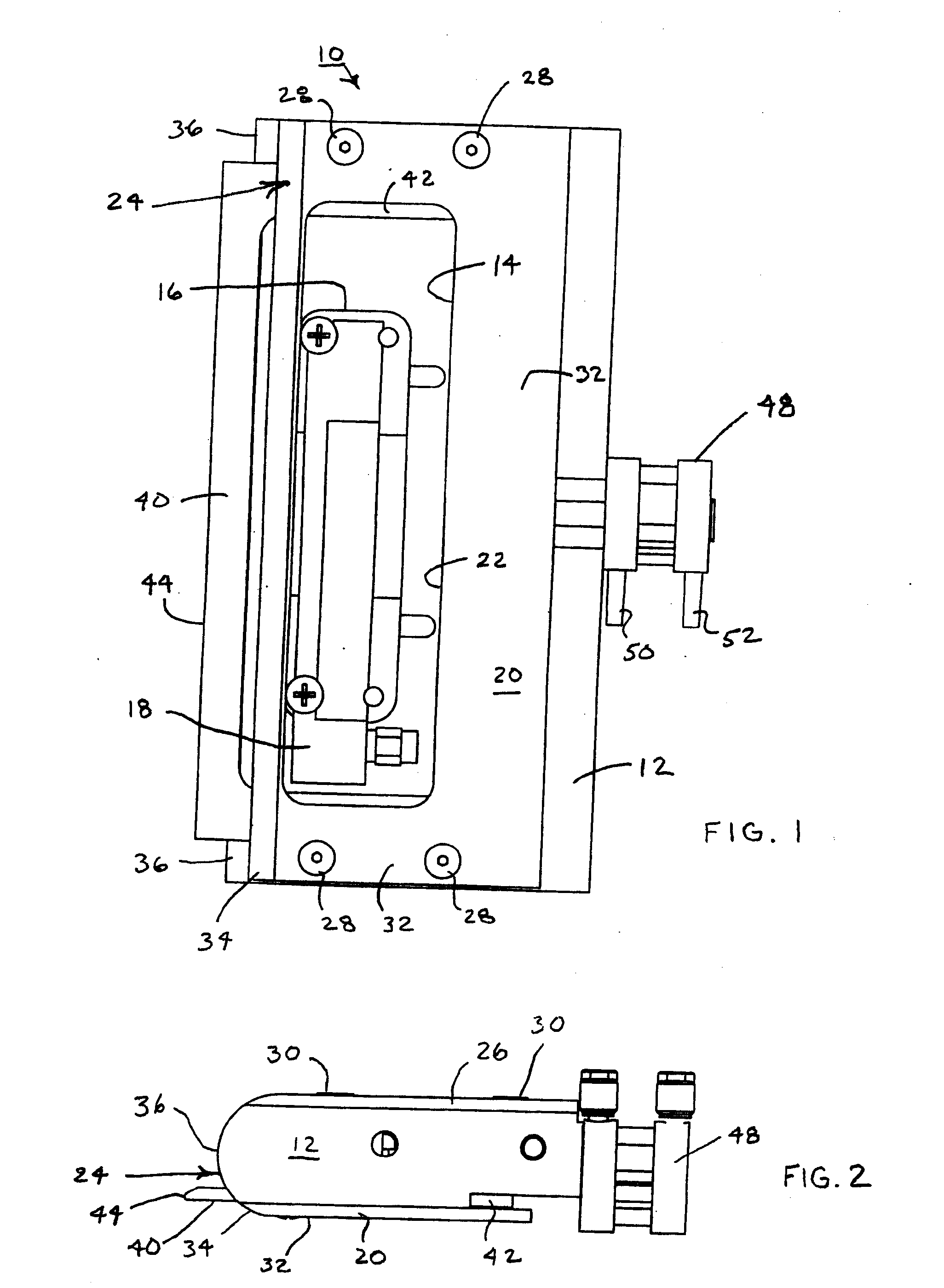
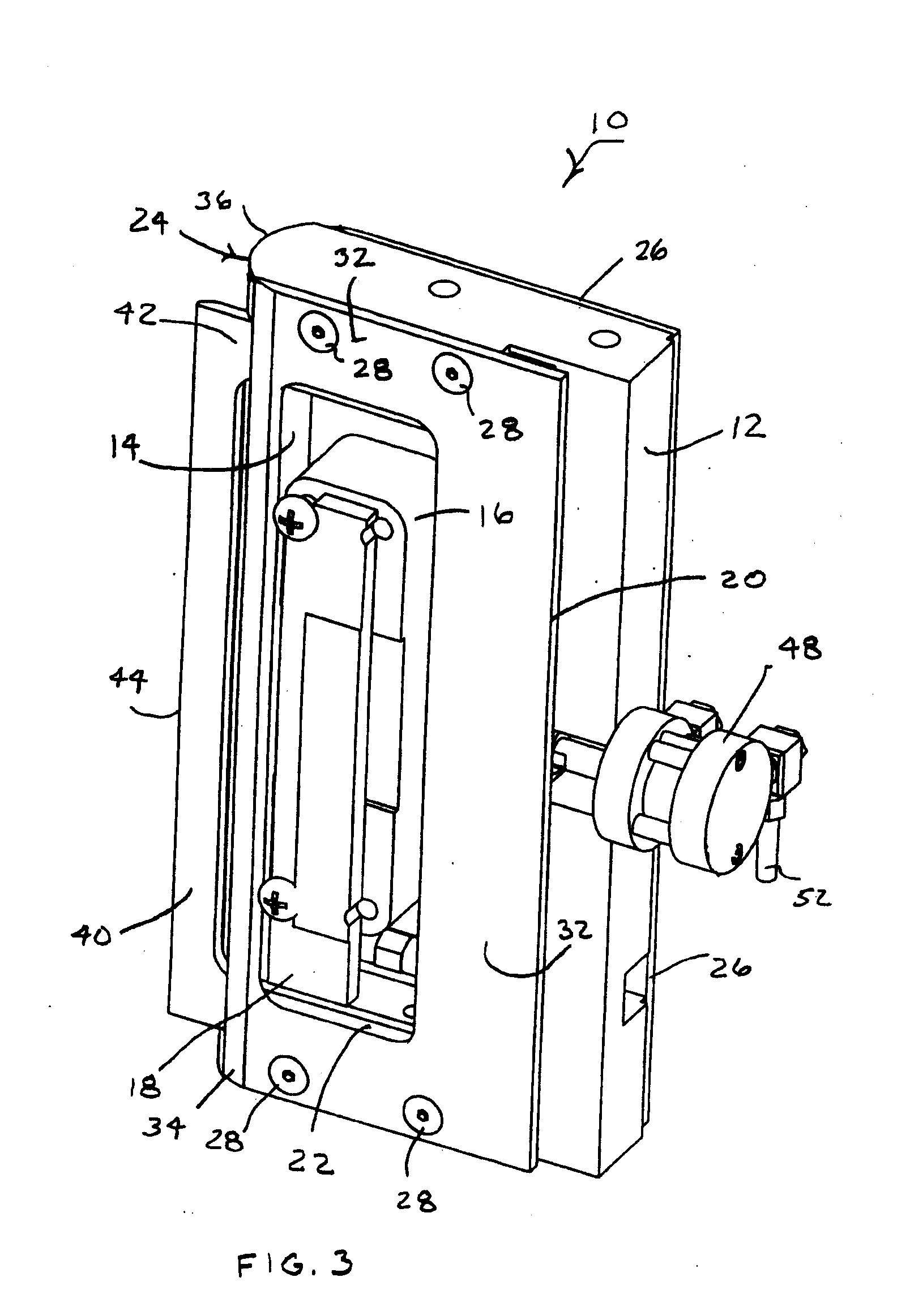
[0024]A peel plate assembly 10 as shown in FIGS. 1-3 is arranged as a preferred embodiment of the invention. The peel plate assembly 10 has a plate body 12 with a through opening in the form of a pocket 14 for receiving a RFID sensor 16 including an antenna 18. A front cover 20, which includes an opening 22 for exposing the antenna 18 within the pocket 14, functions both as a portion of a web guide 24 for directing an RFID tag web (not shown) across the peel plate assembly 10 and as a shield for restricting radio communications with the antenna 18. A back cover 26 mounts the RFID sensor 16 within the pocket 14.

[0025]Both the front cover 20 and the back cover 26 are affixed to the plate body 12 by recessed screws 28 and 30. However, the covers could be affixed in a variety of other ways, or one or both of the front and back covers 20 and 26 could be formed as an uninterrupted integral part of the plate body 12. At least the front cover 20 is preferably made of stainless steel for pur...


PUM

PropertyMeasurementUnit
pressure-aaaaaaaaaa
pressure-sensitiveaaaaaaaaaa
speedsaaaaaaaaaa

Abstract

A peel plate assembly for selectively removing RFID tags from a web for applying the RFID tags to a succession of articles includes an extendible or retractable peel blade and an RFID sensor recess mounted within a plate body. A cover for the plate body functions both as a web guide for advancing a succession of RFID tags past the sensor to the peel blade and as part of a shielding system to isolate communications between the sensor and the closest RFID tag to the peel blade.

Description

BACKGROUND OF THE INVENTION[0001]1. Field of the Invention[0002]The invention relates to the selective application of programmable transponders, such as radio frequency identification devices (RFIDs), to articles, such as product packaging, shipping containers, or products themselves. Peel plate assemblies together with peel blade actuators, and interrogating devices support the selective application of the programmable transponders.[0003]2. Description of Related Art[0004]Programmable transponders, particularly in the form of radio frequency identification devices (RFIDs), are widely used as identification and tracking devices capable of local communications without requiring line of sight access. Information can be written into the programmable transponders and read from the programmable transponders via local transmissions typically in the form of radio waves.[0005]The programmable transponders can be embedded within pressure-sensitive label structures, sometimes referred to as R...

Claims


Application Information

Patent Timeline
Patent Type & Authority Applications(United States)
IPC IPC(8): B65C9/18
CPCB65C2009/404B65C9/1869Y10T29/49004B65C2009/0093B65C2009/0003
Inventor ANGEL, DONALD W.GLENSKI, JOHN T.
Owner WS PACKAGING GROUP
Why Eureka
Try Eureka