Cryogenic Nozzle

a cryogenic nozzle and nozzle technology, applied in the direction of combustion types, heat treatment apparatus, container discharging methods, etc., can solve the problems of reduced spray velocity, flow rate pulsation, and increased boil-off,

Active Publication Date: 2008-02-28
AIR PROD & CHEM INC
View PDF55 Cites 36 Cited by
  • Summary
  • Abstract
  • Description
  • Claims
  • Application Information

AI Technical Summary

Benefits of technology

[0039]An important advantage of the present invention is ability to control the discharged fluid's liquid component is achieved without a conventional flow-restricting valve and the associated pressure drop. Consequently, unlike the conventional methods, the liquid spray velocity in the present invention does not decay as the liquid component of the discharge is reduced (hereafter, the “spray velocity” feature).

Problems solved by technology

A problem with this conventional method is the pressure drop the liquid incurs across the valve which causes a reduction in the spray velocity.
Furthermore, the pressure drop causes a portion of the liquid to boil downstream of the valve which can plug the nozzle and / or the nozzle passage, thereby causing flow rate pulsations.
In particular, a larger nozzle orifice in the conventional method would require a higher degree of valve restriction to achieve an equivalent range of flow reductions, and thus a larger pressure drop and even more boil-off.
This constraint on increasing the nozzle size in the conventional method leads to another problem in the conventional method when the nozzle and the delivery line thereto must be cooled down from room temperature before start-up.
Consequently, the conventional method is faced with the dilemma of choosing between the time-consuming task of changing out the oversized nozzle before commencing normal operation, or the complexities of designing a system for temporarily increasing the orifice size of the nozzle during cool-down.
Finally, another problem with the conventional method is the valve itself.
In particular, valves that must handle cryogenic liquids are costly and tend to break down.
Unfortunately, this modification would be impractical in many applications as the controlling valve makes the nozzle too big and bulky to fit in manufacturing machines.
Furthermore, moving the pressure drop to the nozzle discharge does not prevent the reduction in the spray velocity from occurring.

Method used


Image

  • Cryogenic Nozzle
  • Cryogenic Nozzle
  • Cryogenic Nozzle

Examples


Embodiment Construction

[0030]As used herein and in the claims, the following terms shall be defined as follows:

[0031](i) A “cryogenic fluid” means a fluid having a boiling point less than −73° C. at 1 atm pressure.

[0032](ii) A “cryogenic liquid” means a cryogenic fluid in liquid phase a boiling point less than −73° C. at 1 atm pressure.

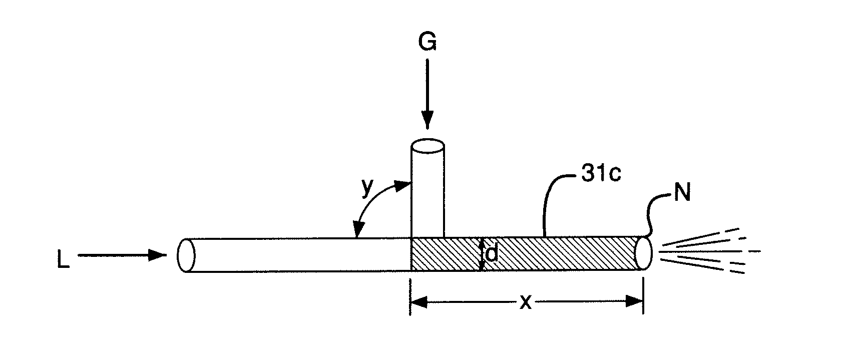
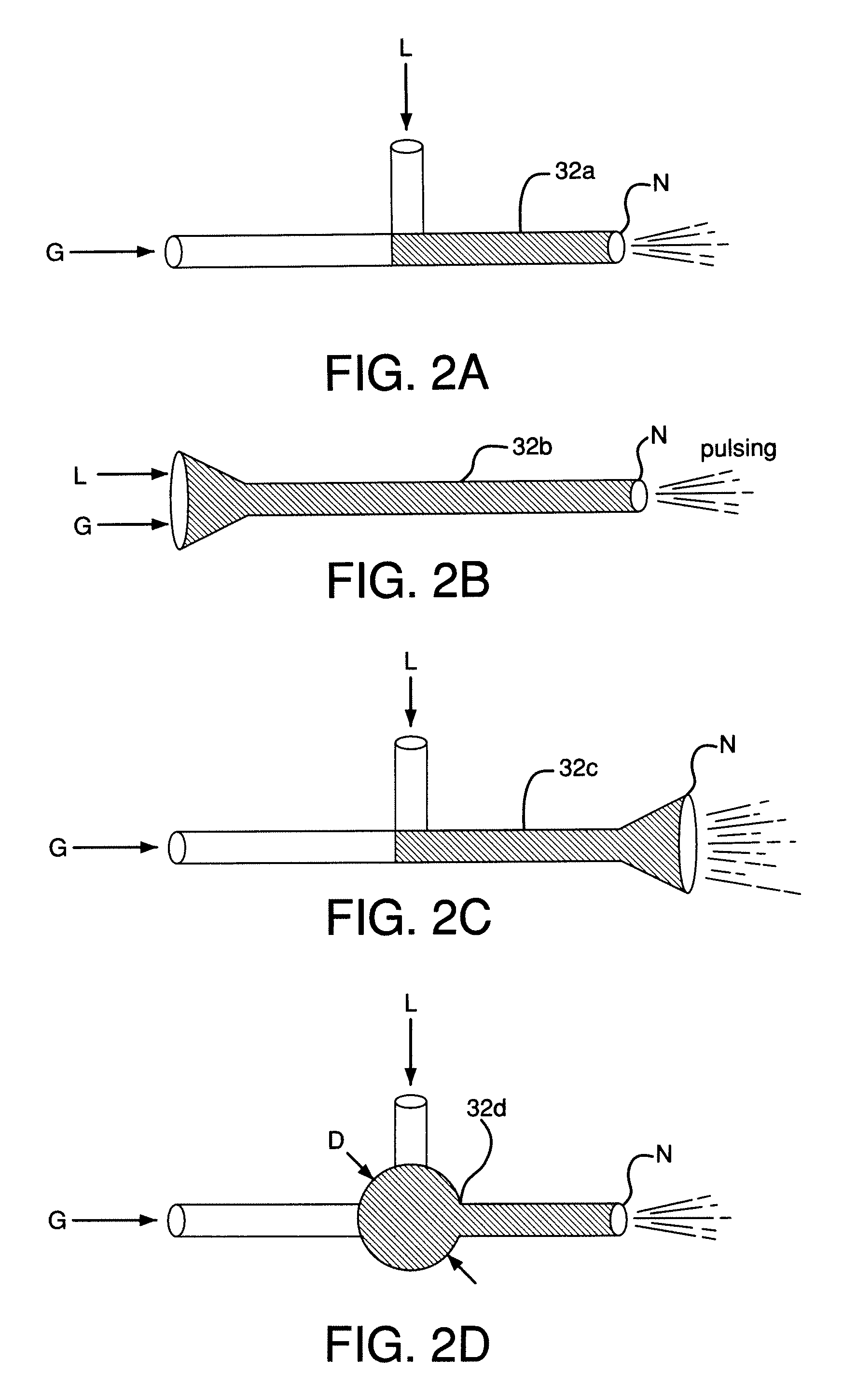
[0033](iii) A “nozzle” shall mean one or more openings for discharging a fluid. A nozzle is a constriction of the fluid line at or near the exit or termination point from which that fluid is ejected into open space that is at a lower pressure than the pressure in the supply line.

[0034](iv) “Head-on” flow communication between a conduit and a nozzle shall mean the flow path at the discharge end of the conduit merges into the flow path through the nozzle without a change in direction. Similarly, “head-on” flow communication between a fluid and a conduit shall mean the flow path of the fluid merges into the flow path at the feed or upstream end of the conduit without a change ...


PUM

PropertyMeasurementUnit
pressureaaaaaaaaaa
angleaaaaaaaaaa
angleaaaaaaaaaa

Abstract

A nozzle and process are set forth for contacting a cryogenic liquid and a gas, and discharging the resulting fluid through the nozzle. In one embodiment, the ratio of the discharged fluid's liquid component to its gaseous component is controlled as a function of the gas pressure.

Description

CROSS-REFERENCE TO RELATED APPLICATIONS[0001]This application claims the benefit of Provisional U.S. Application No. 60 / 840,616 filed Aug. 28, 2006, and 60 / 851189 filed Oct. 12, 2006, both entitled “Nozzle, System, and Method for Cryogenic Impingement” which are incorporated in their entirety herein by reference.BACKGROUND[0002]The present invention relates to a cryogenic nozzle. In particular, the present invention relates to controlling the flow rate of a cryogenic liquid through a cryogenic nozzle. A nozzle is a constriction of the fluid line at or near the exit or termination point from which that fluid is ejected into open space that is at a lower pressure than the pressure in the supply line. The fluid passages shown in FIGS. 1C, 2A-2D and 3 are the constrictions within the nozzle and those figures do not show the supply lines to the nozzle.[0003]FIG. 1A shows the conventional method for controlling the flow rate of a cryogenic liquid through a nozzle. In particular, a valve V...

Claims


Application Information

Patent Timeline
Patent Type & Authority Applications(United States)
IPC IPC(8): B05B7/04
CPCC23C4/121B05B7/1281C21D1/667F17C13/00C23C4/123B05B12/12B05B7/04B05B7/12B05D3/04
Inventor ZURECKI, ZBIGNIEWKNORR, ROBERT ELLSWORTHGREEN, JOHN LEWIS
Owner AIR PROD & CHEM INC
Why Eureka
Try Eureka