
Electrostatic actuator device and method of making the device

a technology of electrostatic actuator and actuator, which is applied in the manufacture of capacitors, variable capacitors, fixed capacitors, etc., can solve the problems of high voltage deflection, high electric fields, and changes in device performance or device failur

Inactive Publication Date: 2008-02-28
XEROX CORP
View PDF26 Cites 46 Cited by
  • Summary
  • Abstract
  • Description
  • Claims
  • Application Information

AI Technical Summary

Benefits of technology

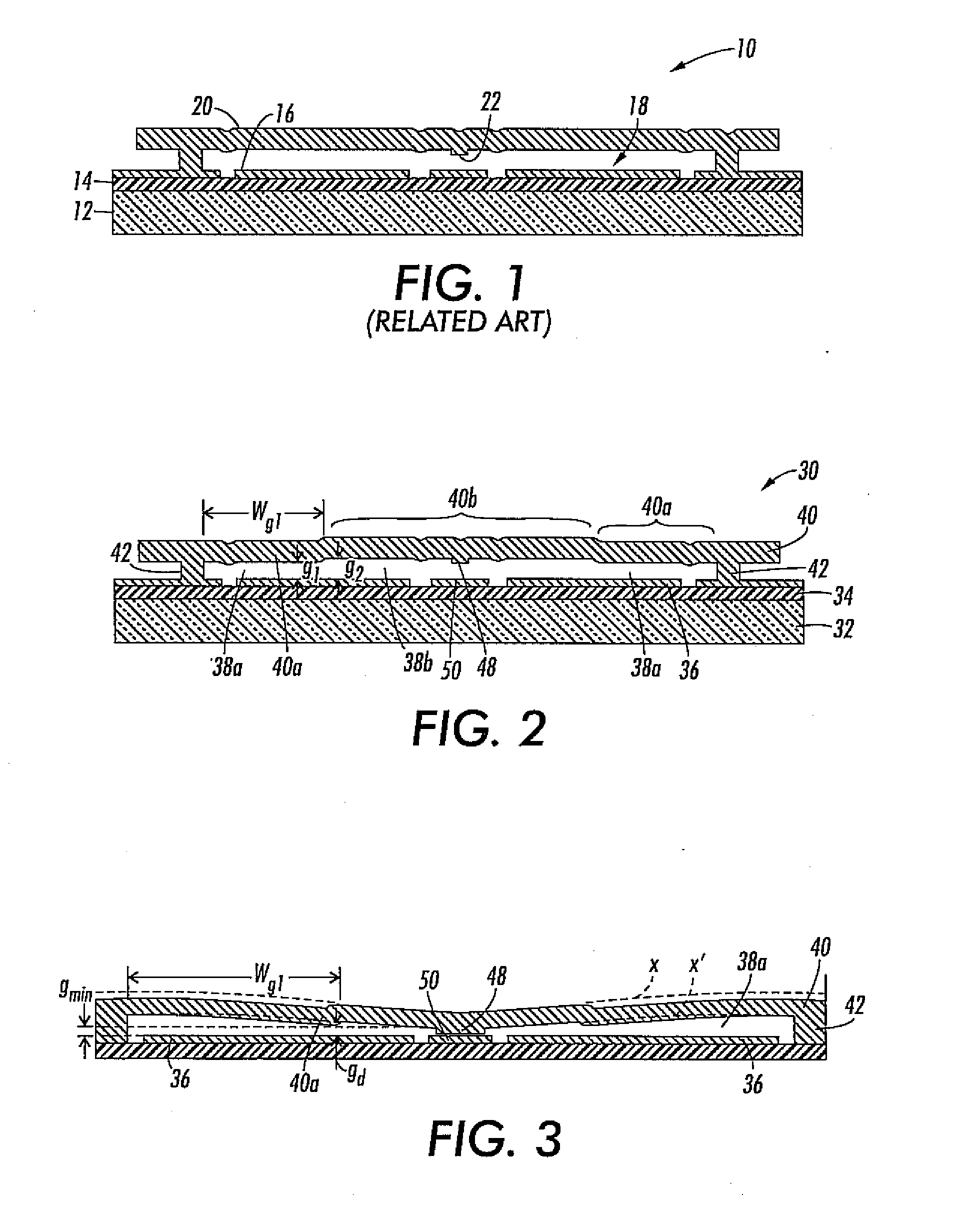
[0006]Membrane 20 may comprise a conductive landing post 22, which often comprises the same material as membrane 20, such as metal or a doped semiconductor. Landing post 22 can aid in reducing problems with stiction, which is a common failure mode in electrostatic actuators, where two surfaces that come into contact become permanently attached by Van der Waals forces. Because landing post 22 reduces the amount of membrane surface area that can come into contact with other surfaces of the device, stiction forces are decreased.

Problems solved by technology

However, when actuating the electrostatic membrane actuator, high voltages are often required to deflect membrane 20.
These high voltages can lead to very high electric fields over the submicron gap, and a variety of failure modes can be created.
Such failure modes can include, for example, dielectric breakdown of air, or other dielectrics, in the gap, or charging of the dielectric, which can lead to changes in device performance or device failure.
In addition, the high voltage circuitry required to drive such devices is often relatively large, and thus more costly, than if smaller voltages were used.

Method used


Image

  • Electrostatic actuator device and method of making the device
  • Electrostatic actuator device and method of making the device
  • Electrostatic actuator device and method of making the device

Examples


Embodiment Construction

[0024]Reference will now be made in detail to various exemplary embodiments of the present application, examples of which are illustrated in the accompanying drawings. Wherever possible, the same reference numbers will be used throughout the drawings to refer to the same or like parts.

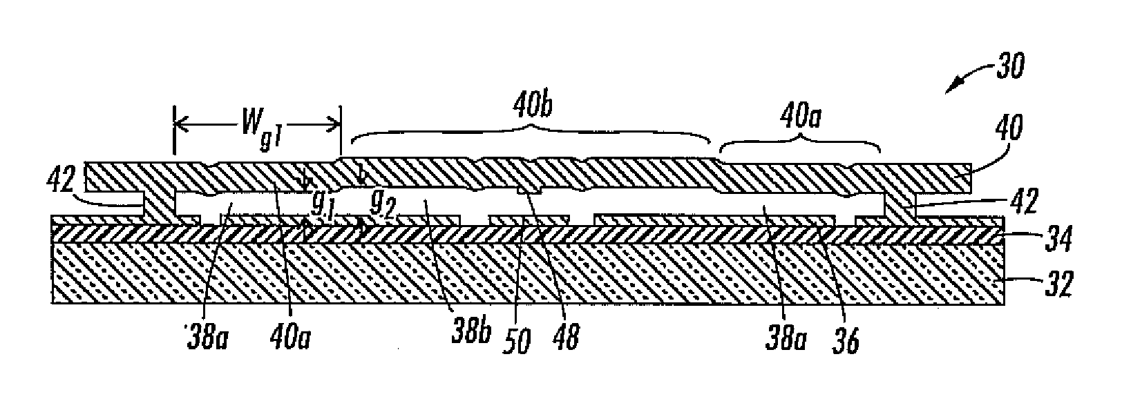
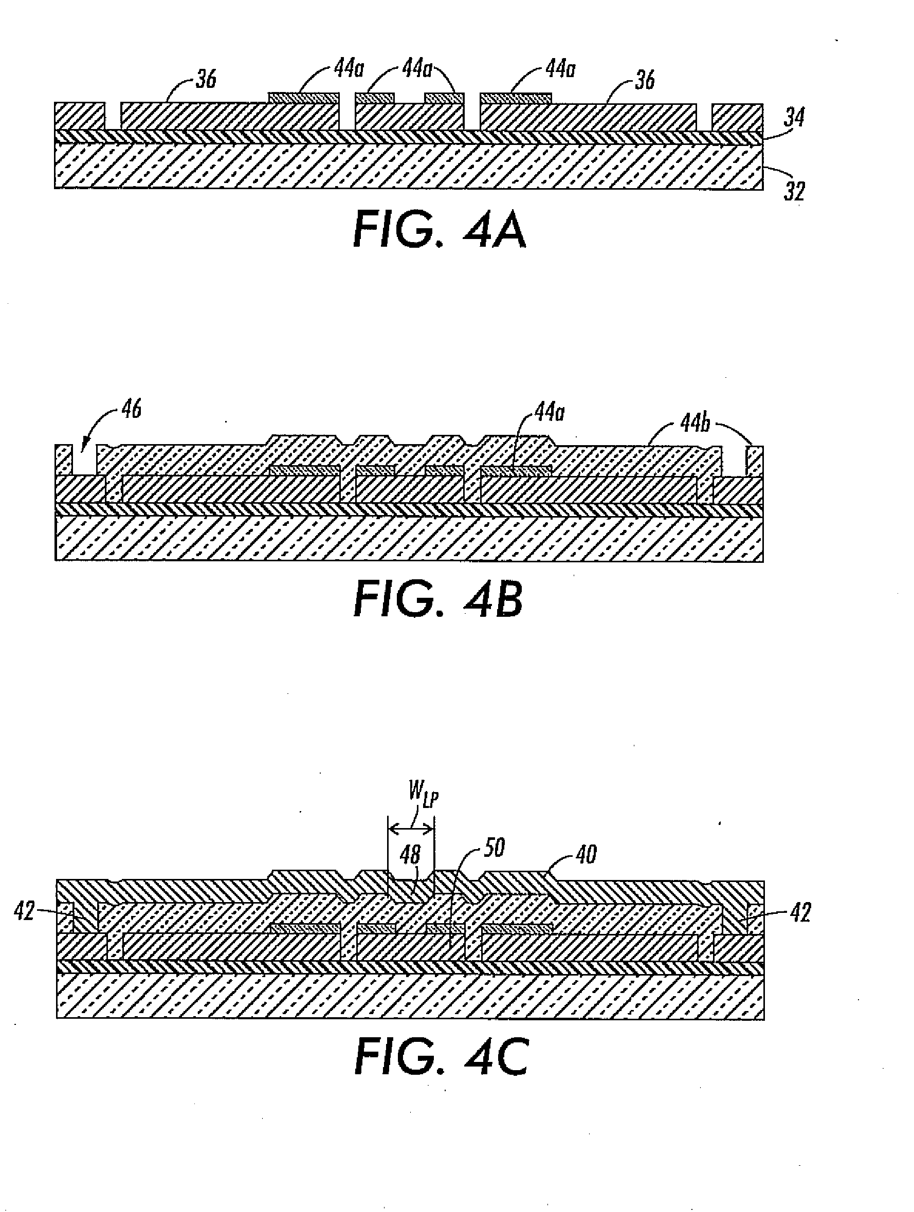
[0025]FIG. 2 illustrates an electrostatic actuator device 30 according to an embodiment of the present application. Electrostatic actuator device 30 can include a substrate 32, an insulator layer 34, an electrode 36, a gap 38 and a deflectable member 40. Deflectable member 40 can be anchored on substrate 32 via anchors 42. For purposes of this application, the term “on” is defined so as not to require direct physical contact, so that neither deflectable member 40 or anchors 42 need be in direct physical contact with substrate 32. In yet other embodiments, anchors 42 may be in direct physical contact with substrate 32.

[0026]Substrate 32 may be any desired material that will provide suitable mechanical s...


PUM


Abstract

The present application is directed to novel electrostatic actuators and methods of making the electrostatic actuators. In one embodiment, the electrostatic actuator comprises a substrate, an electrode formed on the substrate and a deflectable member positioned in proximity to the electrode so as to provide a gap between the electrode and the deflectable member. The deflectable member is anchored on the substrate via one or more anchors. The gap comprises at least one first region having a first gap height positioned near the one or more anchors and at least one second region having a second gap height positioned farther from the anchors than the first region. The first gap height is smaller than the second gap height.

Description

DESCRIPTION OF THE DISCLOSURE[0001]1. Field of the Disclosure[0002]The present application is directed to electrostatic actuators and methods of making electrostatic actuators.[0003]2. Background of the Disclosure[0004]Electrostatic actuators are well known for use in a variety of applications, such as in fluid ejectors for ink jet recording or printing devices. Electrostatic actuators often comprise one or more membranes which can be deflected using electrostatic forces.[0005]FIG. 1 illustrates one example of an electrostatically actuated membrane device 10 in a relaxed state. Membrane 10 can comprise a substrate 12, an insulator layer 14, a stationary electrode 16, a gap 18 and a membrane 20. Substrate 12 can be, for example, a silicon wafer. Insulator layer 14 can be, for example, thin film insulators, such as, silicon nitride. Stationary electrode 16 and membrane 20 may comprise, for example, a metal or a doped semiconductor, such as doped polysilicon. Gap 18 often comprises air...

Claims


Application Information

Patent Timeline
Patent Type & Authority Applications(United States)
IPC IPC(8): H01G9/00H01H57/00
CPCH01H59/0009H01G5/18
Inventor GULVIN, PETER M.NYSTROM, PETER J.
Owner XEROX CORP
Learn More