Rectangular-wave transmitting metal detector

a metal detector and rectangular wave technology, applied in the field of electronic metal detectors, can solve the problems of relatively high cost of electronics in such detectors, and achieve the effect of high efficiency

Inactive Publication Date: 2008-02-28
MINELAB ELECTRONICS
View PDF5 Cites 9 Cited by
  • Summary
  • Abstract
  • Description
  • Claims
  • Application Information

AI Technical Summary

Benefits of technology

[0018] Thus the new proposed PI-like waveform offers advantage of producing a wide-band transmis

Problems solved by technology

The electronics in such detector

Method used


Image

  • Rectangular-wave transmitting metal detector
  • Rectangular-wave transmitting metal detector
  • Rectangular-wave transmitting metal detector

Examples


Embodiment Construction

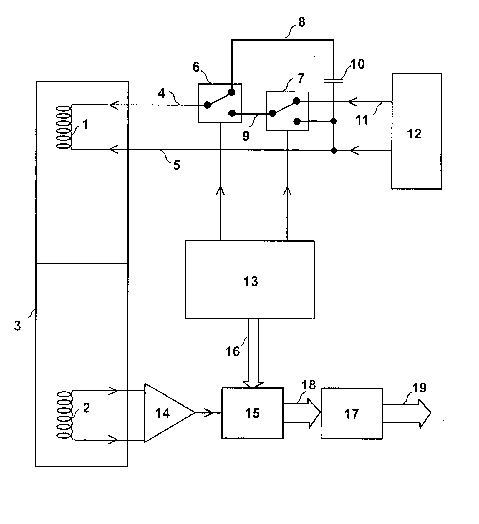
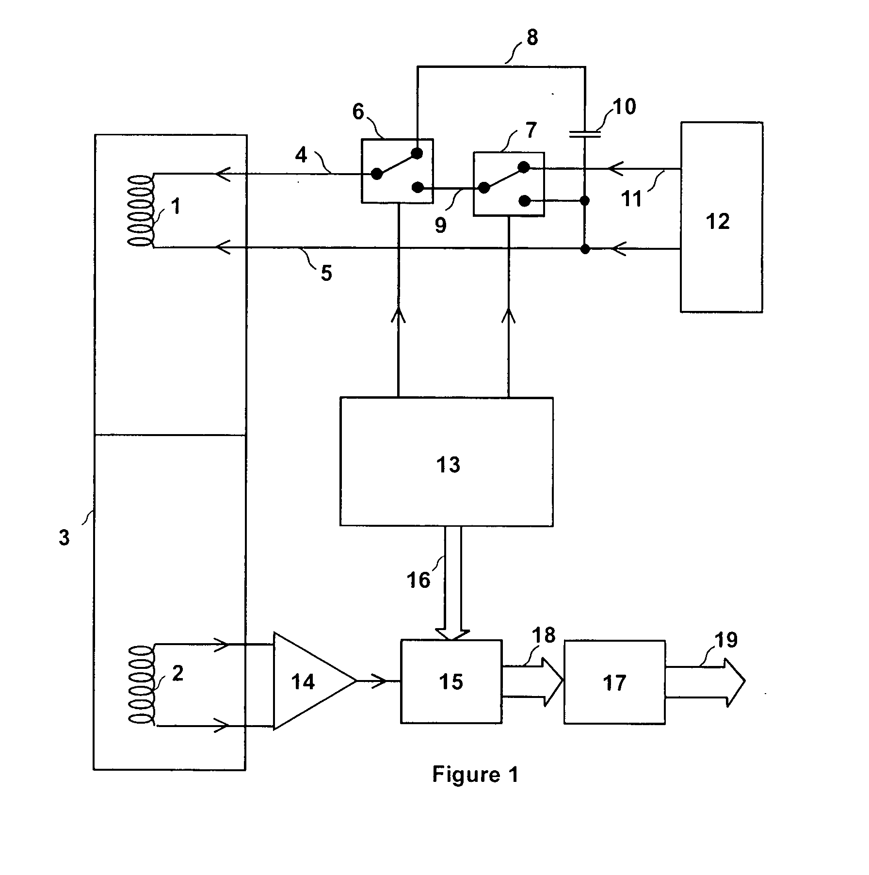
[0022] Referring now to FIG. 1, where there is illustrated an electronic metal detector having transmit electronics (4, 5, 6, 7, 8, 9, 10, 11, 12 and 13), which includes switching electronics consisting of switch 6 and switch 7, both controlled by timing electronics 13. When operational, a transmit signal appears across output 4 and output 5, which is connected to a transmit coil 1, which transmits a resulting alternating magnetic field. A second power source 12 supplies a second voltage output at 11 and 5, and a first power source consists of a capacitor 10, whose energy is provided by a back-emf of the transmit coil switched to the storage capacitor by the said switching electronics, the charge within the storage capacitor being increased and decreased as energy is transferred back and forth between the said storage capacitor and the transmit coil, which results in a first voltage appearing across capacitor 10. When switch 6 selects output 8, that is capacitor 10, the first voltag...


PUM


Abstract

This invention relates to an electronic metal detector having transmit electronics comprising switching electronics arranged and adapted to generate a transmit signal, the transmit electronics comprising at least two power sources, a first power source and a second power source, the transmit electronics being connected to a transmit coil arranged and adapted to transmit an alternating magnetic field, wherein the switching electronics are adapted and arranged to switch a first voltage of the first power source to the transmit coil for at least a first period and also a third period, the switching electronics being adapted and arranged to switch a second voltage of the second power source to the transmit coil for at least a second period. The switching electronics are further adapted and arranged to switch approximately zero volts to the transmit coil for at least a fourth period, the second voltage being opposite in polarity to the first voltage, and an absolute magnitude of the first voltage being at least ten times an absolute magnitude of the second voltage, the said first voltage, second voltage, first period, second period and third period and fourth period being selected so that a transmit coil current increases in a second polarity sense during the second period and changes sign during the second period, and the transmit coil current increases in an opposite polarity sense to the second polarity sense during the first period and also the third period, receive electronics is adapted and arranged to receive and process a receive magnetic field during at least some of the second period and fourth period to produce an indicator output, the indicator output at least indicating the presence of at least some metal targets under the influence of the said alternating magnetic field and indicating at least a characteristic of the metal targets.

Description

TECHNICAL FIELD [0001] The current invention relates to a electronic metal detector and a method for using the same, where the metal detector transmits a repeating switched rectangular-wave voltage sequence and has particular application to hand-held coin, treasure, prospecting and landmine, coin and treasure detectors. BACKGROUND ART [0002] In this specification unless the contrary is expressly stated, where a document, act or item of knowledge is referred to or discussed, this reference or discussion is not to be construed as an admission that the document, act or item of knowledge or any combination thereof was at the priority date, publicly available, known to the public, part of common general knowledge; or known to be relevant to an attempt to solve any problem with which this specification is concerned. [0003] Most commercial metal detectors operate in comprising most handheld metal detectors designed to hunt for buried metal targets such as gold, coins, treasure and archaeol...

Claims


Application Information

Patent Timeline
IPC IPC(8): G01V3/08
CPCG01V3/104
Inventor CANDY, BRUCE HALCRO
Owner MINELAB ELECTRONICS
Why Eureka
Try Eureka