Domino Circuit with Master and Slave (DUAL) Pull Down Paths

a domino circuit and master slave technology, applied in logic circuits, pulse techniques, electrical apparatus, etc., can solve problems such as relative slowness and noise, prior art domino circuits have problems with speed and noise, and have undesirable characteristics, and achieve reliable and stable output signals.

Inactive Publication Date: 2008-02-28
IBM CORP
View PDF1 Cites 2 Cited by
  • Summary
  • Abstract
  • Description
  • Claims
  • Application Information

AI Technical Summary

Benefits of technology

[0018]The invention relates to a novel dynamic or domino type circuit having a Master transmission path and a Slave transmission path connected to a master and virtual evaluation nodes, respectively. The Master transmission path includes n NMOS transistors or n NFET arranged in a stack. Each of the n NFET has an input to receive in input signal (IN1, IN2 . . . INn). The Slave transmission path includes at least one NFET with an input to receive a clock signal. A current mirror, preferably formed by two NFETS, couples the Master transmission path to the Slave transmission path. A PFET with an input to receive a clock signal is operatively connected to the virtual evaluation node. An inverter with an output on which an output signal is provided is operatively connected to the virtual evaluation node. The master evaluate on node is driven by a clocked PFET. By separating the evaluation node and connecting the output stage to the virtual evaluation node a more reliable and stable output signal is provided.

Problems solved by technology

Although the prior art domino circuit of FIG. 1 works well for its intended use, it is relatively slow and susceptible to noise.
Stated another way, the prior art domino circuits have problem with speed and noise.
Even though the circuit is an improvement over prior art circuit discussed above and shown in FIG. 1, it too has some undesirable characteristics.
This configuration creates a noise condition, which permits the unwanted current flow between two paths during evaluation phase.
The consequence of this noise condition would degrade the rate of discharge on the evaluation node.
Generally, two discharge paths should never be dotted together when they are coupled with a current mirror device; because this circuit topology will cause unexpected performance degradation.

Method used


Image

  • Domino Circuit with Master and Slave (DUAL) Pull Down Paths
  • Domino Circuit with Master and Slave (DUAL) Pull Down Paths
  • Domino Circuit with Master and Slave (DUAL) Pull Down Paths

Examples


Embodiment Construction

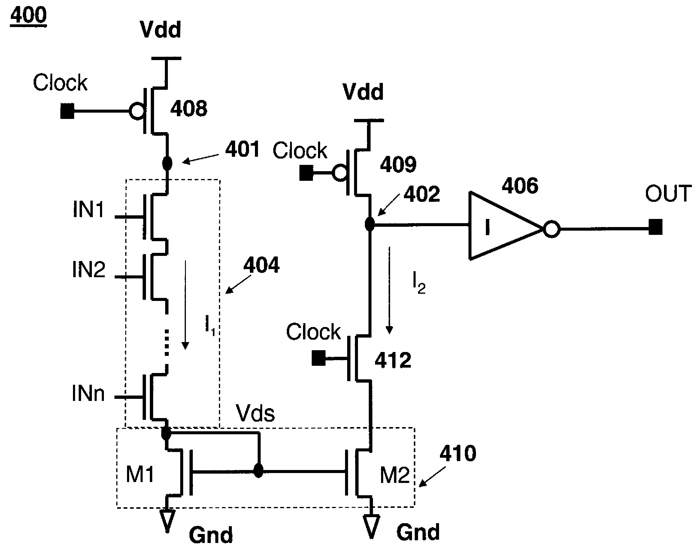
[0025]The present invention presents a domino style circuit in which a current mirror coupling a slave transmission control path and master transmission path discharge a virtual evaluation node and master evaluation node, respectively. This approach solves problem in prior art domino style circuits. Before describing details of the circuit according to teachings of the present invention, a description of the problem which the inventor discovers and solve will be given. As a consequence, the discovery of the problem is part of the present invention.

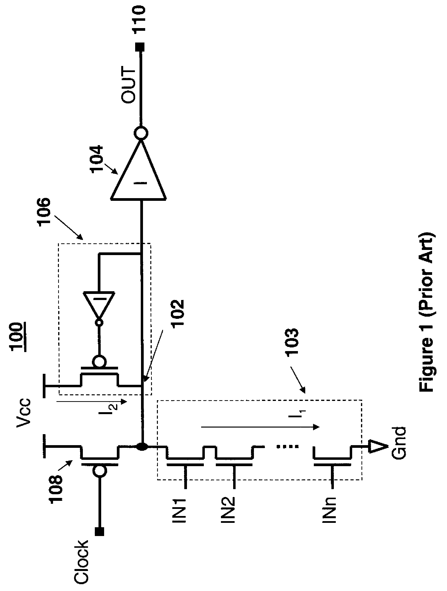
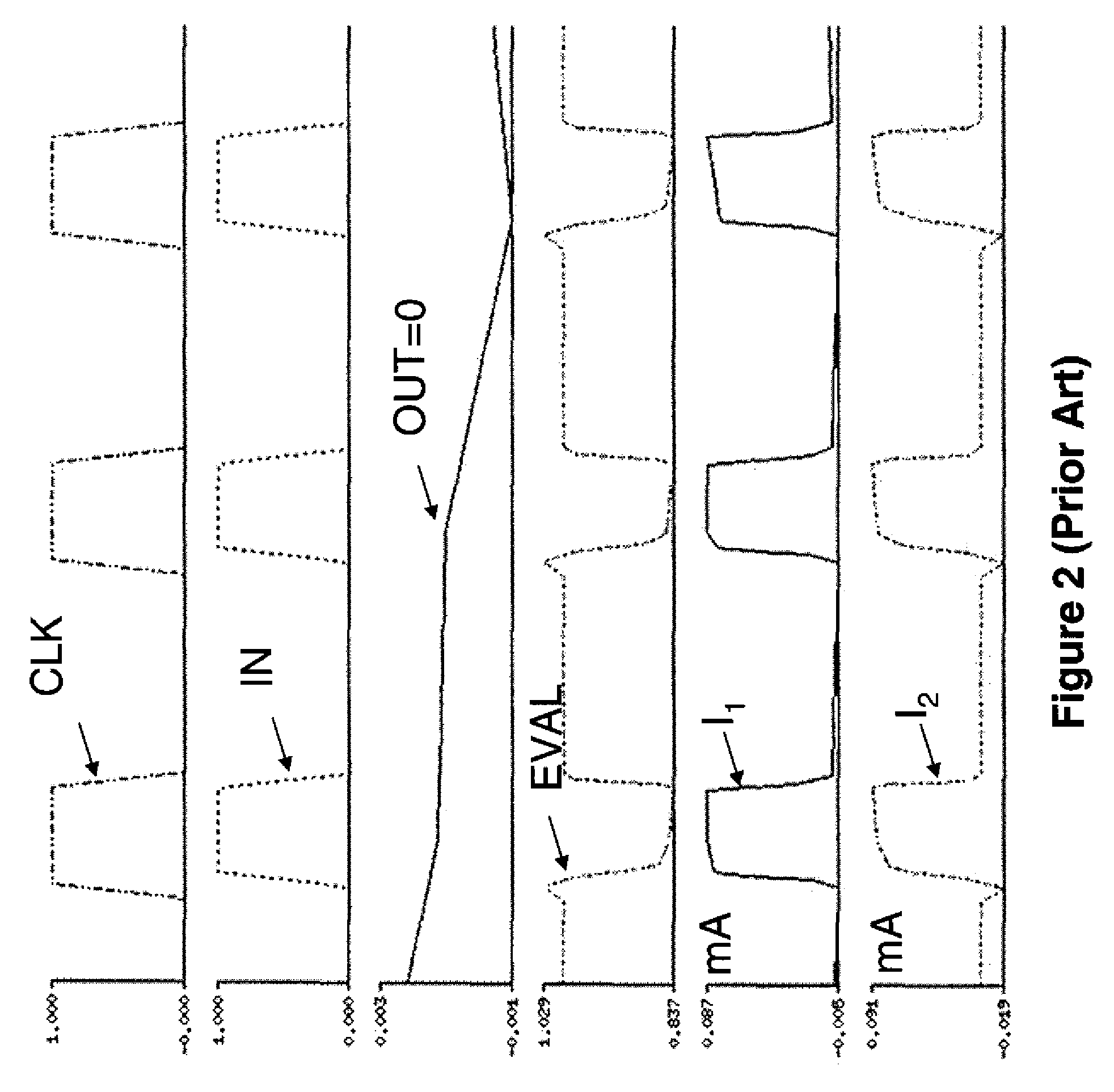
[0026]FIG. 1 shows the prior art domino type circuit having pulled down network 103 and keeper circuit 106 connected to a single evaluation node 102. The pulled down network 103 consists of a plurality of NFET stacked or connected in series to evaluation node 102. Current I2 flows in keeper circuit 106 and current I1 flows in pulled down network 103. During the evaluation phase when the clock single is high (logical “1”) I1 and I2 could ca...


PUM


Abstract

A domino circuit and method include a master evaluation node to which a master discharge path with a wide input AND gate is coupled and a virtual evaluation node to which an output stage and slave discharge path are coupled. A current mirror interconnects the master discharge path and the slave discharge path. The devices in the current mirror are sized so that current flowing in the master discharge path is amplified into the slave transmission path.

Description

CROSS-REFERENCE TO RELATED APPLICATIONS[0001]The present application relates to application Ser. No. ______ (RPS92006028US 1 (4193), assigned to the assignee of the present invention and filed concurrently herewith.BACKGROUND OF THE INVENTION[0002]1. Field of the Invention[0003]The present invention relates to integrated circuits, in general and, in particular, to dynamic or domino logic circuits.[0004]2. Background Art[0005]The use of domino logic circuits is well known and documented in the prior art. Such circuits are used to generate particular functions in processors and like electronic devices. In order to generate a particular function, several stages of domino logic circuits are usually coupled or concatenated. In this configuration, one stage provides input to the next stage and so forth.[0006]FIG. 1 shows a schematic for a single stage conventional domino circuit 100 consisting of evaluation node 102 to which output stage 104, leakage tolerant keeper 106, pull down network...

Claims


Application Information

Patent Timeline
Patent Type & Authority Applications(United States)
IPC IPC(8): H03K19/096
CPCH03K19/0963
Inventor CHENG, ZHIBIN
Owner IBM CORP
Why Eureka
Try Eureka