Detecting movement of a computer device to effect movement of selected display objects

a computer device and display object technology, applied in computing, portable computers, instruments, etc., can solve the problems of limiting the usefulness and range of functions that can be performed, known techniques suffer from various drawbacks and limitations, and fail to consider the use of movement detection to control display objects in a multi-display environmen

Inactive Publication Date: 2008-02-28
APPLE INC
View PDF10 Cites 47 Cited by
  • Summary
  • Abstract
  • Description
  • Claims
  • Application Information

AI Technical Summary

Benefits of technology

[0011]The systems and methods of the invention relate to providing a computer device, having a display unit, with an accelerometer (or other motion sensor) to detect movement of the computer device (and / or an associated display unit) and generate movement data. An accelerometer driver may receive the generated movement data. The generated movement data may be processed and / or interpreted in order to create one or more control signals. The control signals may be sent to a display driver to control movement of one or more selected display objects on one or more display units. The control signals may control movement of selected display objects on a screen display (or between multiple screen displays) associated with the computer device.
[0012]The accelerometer may be included within or on the computer device itself. The accelerometer may be used to detect movement of the computer device, including in some examples, the display unit itself. This may occur, for example, when the computer device and the display unit are connected together (e.g., in a laptop or other device). The accelerometer may generate movement data based on the detected movements. The generated movement data may include movement information relating to tilt, orientation, speed and duration of movement, among other things. The movement information may also include information relating to movement in x-y-z directions (and / or other coordinate systems). The movement data may be output to an accelerometer driver. The accelerometer driver may substantially continuously process and / or interpret the detected movement data (e.g., to mimic a mouse, joystick or other input device) and supply substantially continuous control signals to a CPU of the computer device. The CPU device, through one or more display drivers, may control the movement and / or position of the one or more selected display objects based on the received control signals.
[0013]According to one aspect of the invention, one or more display objects, within a single display screen, may be selected (using any suitable selection technique). Based on detected movements and corresponding movement data of the computer device and / or the associated display unit itself, the one or more selected display objects may move relative to one or more other display objects within the single display screen (instead of, for example, rotating an entire display).
[0014]According to another aspect of the invention, in a multi-display environment, movement data for the computer device may be used to control movement of one or more selected display objects (e.g., from one display to another).
[0015]According to another aspect of the invention, in the context of a 3-dimensional display, movement data for the computer device may be used to control the 3-d display.

Problems solved by technology

These known techniques suffer from various drawbacks and limitations.
For example, the limited, discrete detection data (side to side, back to front or 90 degree orientation) limits the usefulness and range of functions that can be performed using movement of the computer device as an input mechanism.
But more precise and continuous control of movement relating to individually selected display objects (e.g., individual objects within a screen display) is typically not available.
Additionally, these systems also fail to consider use of movement detection to control display objects in a multi display environment.

Method used


Image

  • Detecting movement of a computer device to effect movement of selected display objects
  • Detecting movement of a computer device to effect movement of selected display objects
  • Detecting movement of a computer device to effect movement of selected display objects

Examples


Embodiment Construction

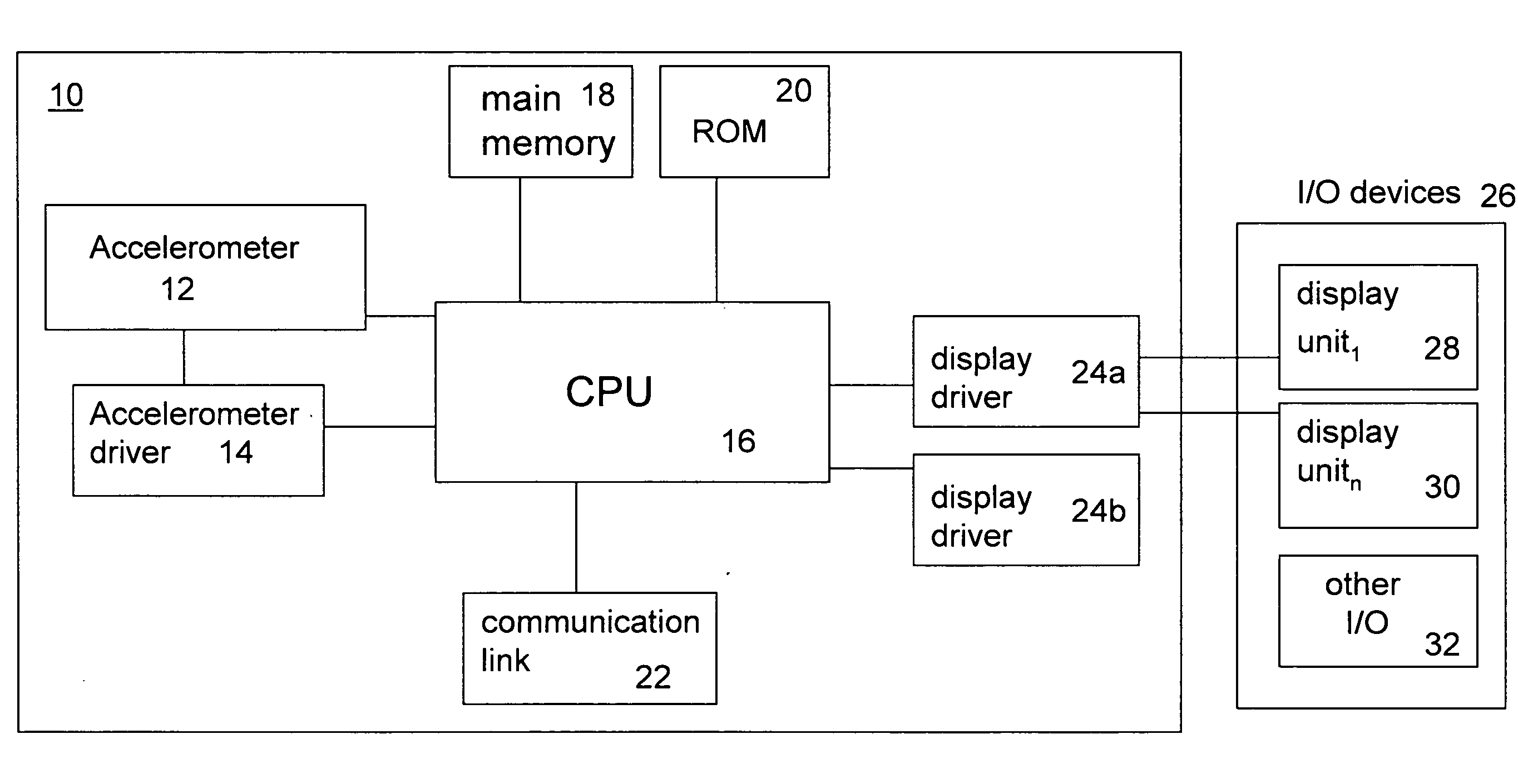
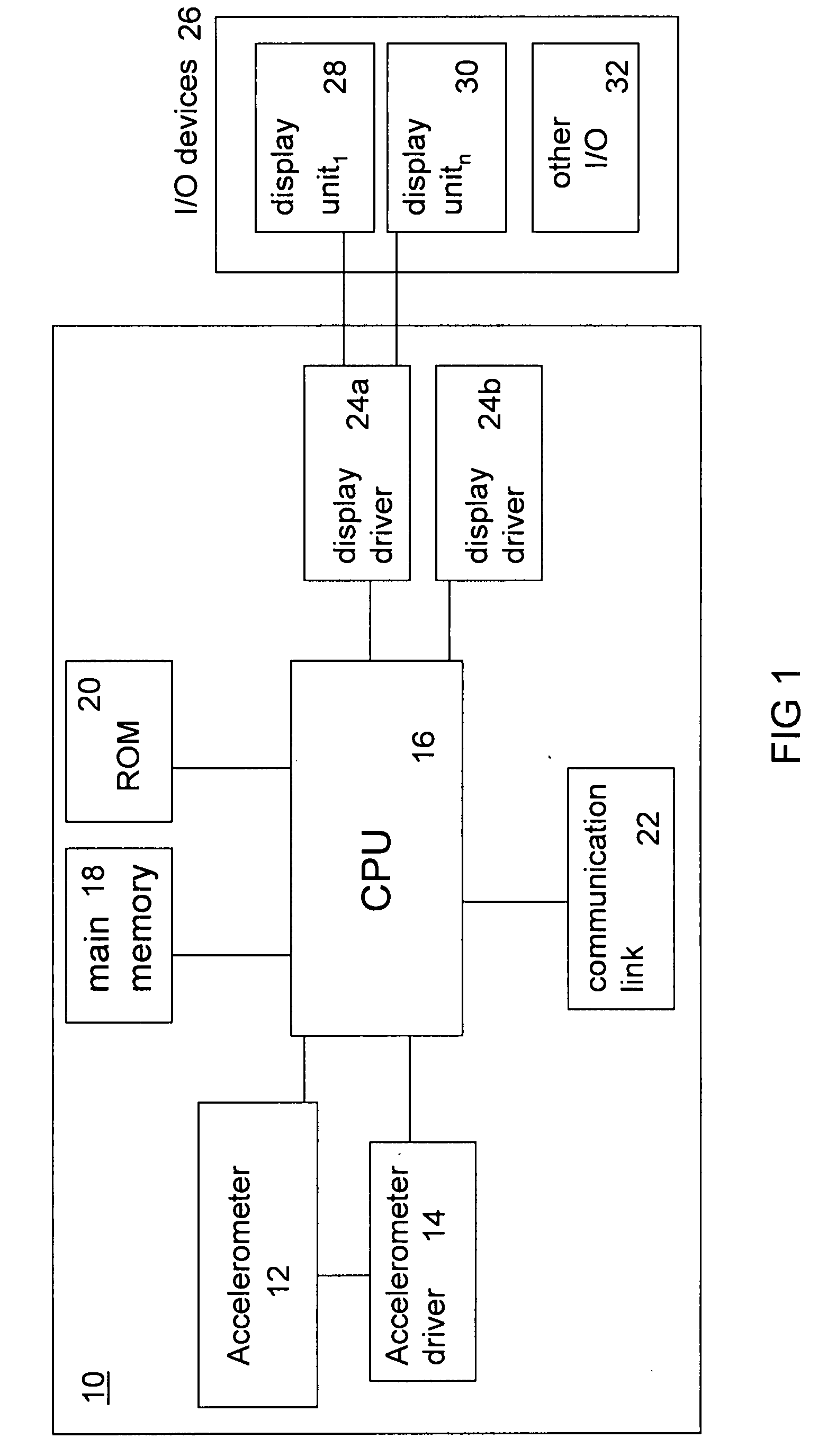
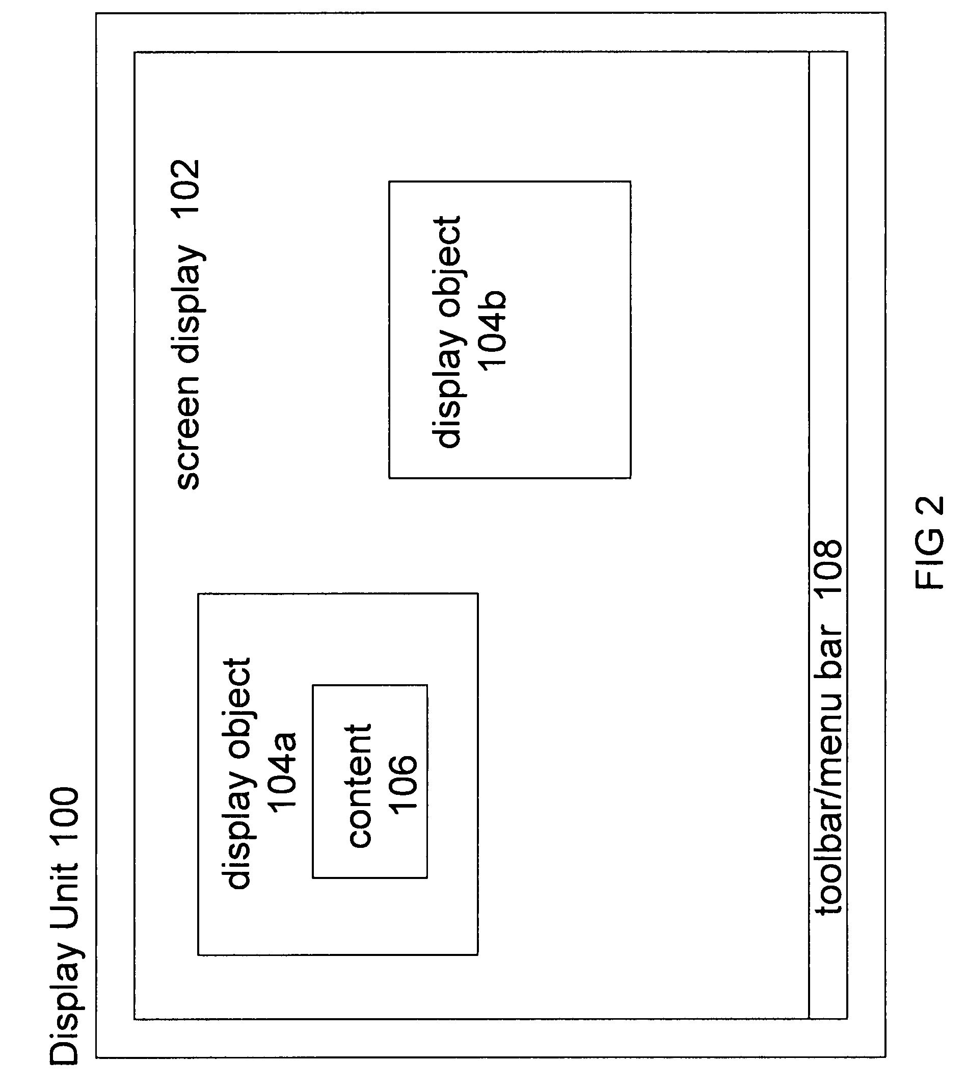
[0023]The systems and methods of the invention relate to providing a computer device, having a display unit, with an accelerometer (or other motion sensor) to detect movement of the computer device (and / or an associated display unit) and generated movement data based on the detected movement. The movement data may be processed and / or interpreted in order to created one or more control signals. The control signals control movement of selected display objects on a screen display (or between multiple screen displays) associated with the computer device.

[0024]The system of the invention may include among other things, a computer device 10, accelerometer 12, accelerometer driver 14, device CPU 16, main memory 18, ROM 20, communication link 22, display drivers (24a, 24b,) I / O devices 26 including display unit(s) (28, 30) and / or other input / output devices 32. These components and corresponding software and / or hardware modules collectively may be used to perform a method with respect to det...


PUM


Abstract

The systems and methods of the invention relate to providing a computer device, having a display unit, with an accelerometer (or other motion sensor) to detect movement of the computer device (and/or an associated display unit) and generate movement data. An accelerometer driver may receive the generated movement data. The generated movement data may be processed and/or interpreted in order to create one or more control signals. The control signals may be sent to a display driver to control movement of one or more selected display objects on one or more display units. The control signals may control movement of selected display objects on a screen display (or between multiple screen displays) associated with the computer device.

Description

[0001]This application claims the benefit of U.S. Provisional Application No. 60 / 823,219, filed Aug. 22, 2006, which is herein incorporated by reference in its entirety.BACKGROUND[0002]1. Field of Invention[0003]The invention relates to systems and methods for detecting movement of a computer device and using detected movements to generate movement data and / or control signals to control movement of selected display objects on a screen display or between multiple screen displays associated with the computer device.[0004]2. Background of the Invention[0005]Accelerometers and motion sensors in general are known and are used in various applications. Some computer devices include accelerometers. However, known uses typically relate to security (e.g., detecting unauthorized attempts to move a computer and sounding an alarm in the event unauthorized movement occurs) or hard disk protection when a device is dropped or subject to significant vibration (e.g., locking the hard drive or moving ...

Claims


Application Information

Patent Timeline
Patent Type & Authority Applications(United States)
IPC IPC(8): G06F3/033
CPCG06F1/1613G06F1/1694G06F2200/1637G06F3/0346G06F3/017
Inventor LOVE, ROBERTFRIEDMAN, NATHANIEL DOURIFREVEMAN, DAVID
Owner APPLE INC
Why Eureka
Try Eureka