Technique for protecting against failure of a network element using Multi-Topology Repair Routing (MTRR)

a network element and multi-topology technology, applied in the field of computer networks, can solve the problems of resetting the network, redirecting traffic, and affecting so as to prevent extended and unwarranted mtr topology cross-over and maintain the integrity of the network

Active Publication Date: 2008-02-28
CISCO TECH INC
View PDF20 Cites 120 Cited by
  • Summary
  • Abstract
  • Description
  • Claims
  • Application Information

AI Technical Summary

Benefits of technology

[0022]Advantageously, the novel technique protects against failure of a network element using MTRR in a computer network. By expanding repair path computation to MTR, the novel technique allows repair paths (e.g., for FRR) to be established where not otherwise available to a particular topology. In particular, the novel technique maintains the integrity of MTR (i.e., the distinct topologies) by specifically delineating allowable temporary usage of MTRR paths, thus preventing extended and unwarranted MTR topology cross-over. Further, the dynamic aspects of the novel technique alleviate the need for cumbersome manual configuration.

Problems solved by technology

Since management of interconnected computer networks can prove burdensome, smaller groups of computer networks may be maintained as routing domains or autonomous systems.
Occasionally, a network element (e.g., a node or link) will fail, causing redirection of the traffic that originally traversed the failed network element to other network elements that bypass the failure.
Reconfiguring a network in response to a network element failure using, e.g., pure IP rerouting, can be time consuming.
However, in the event the topology of the protected network element does not have an acceptable repair path, there is currently no known means available for a protecting node to utilize a different topology.

Method used


Image

  • Technique for protecting against failure of a network element using Multi-Topology Repair Routing (MTRR)
  • Technique for protecting against failure of a network element using Multi-Topology Repair Routing (MTRR)
  • Technique for protecting against failure of a network element using Multi-Topology Repair Routing (MTRR)

Examples


Embodiment Construction

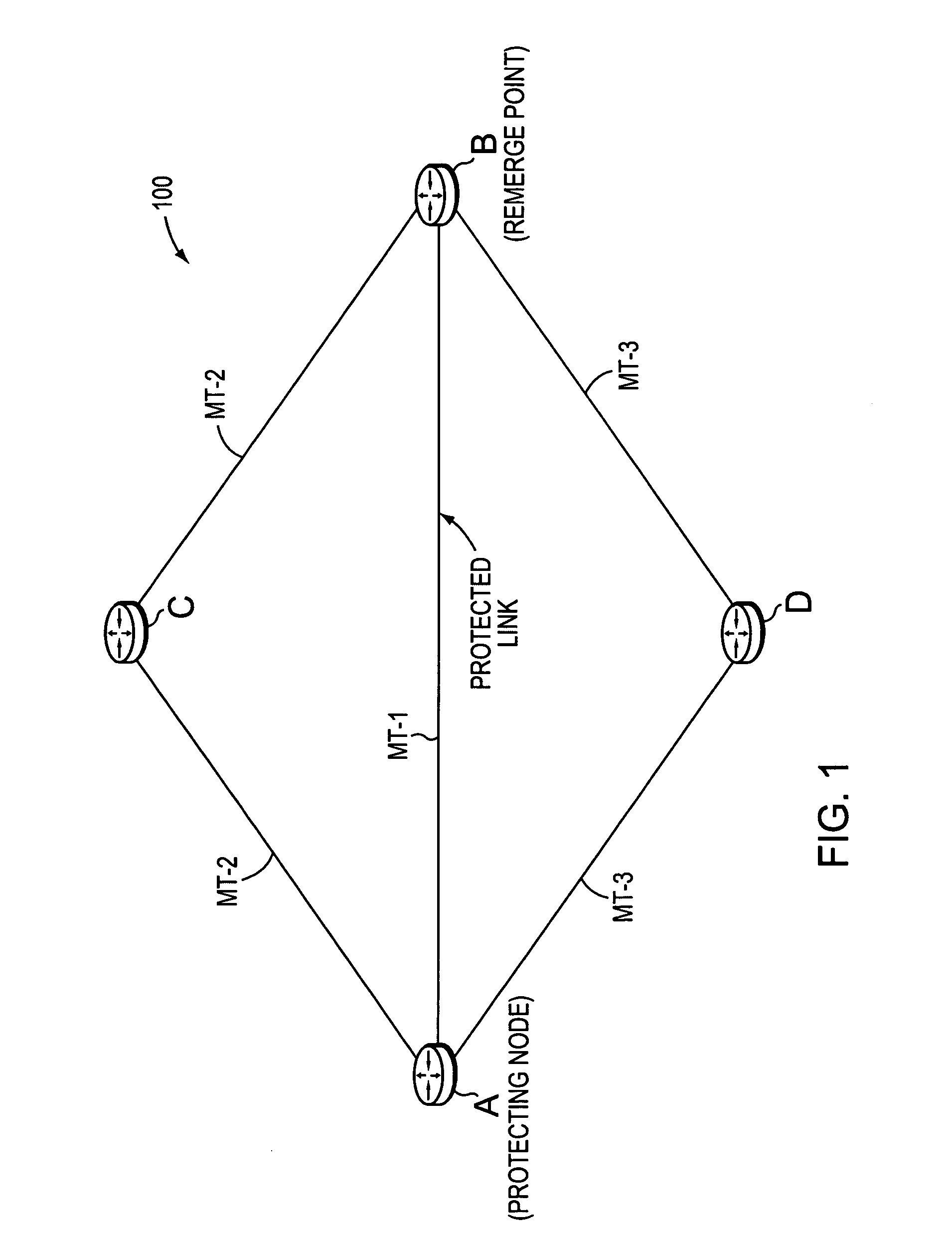
[0031]FIG. 1 is a schematic block diagram of an exemplary computer network 100 that may be advantageously used with the present invention. The network 100 comprises a plurality of interconnected network nodes / devices, such as Routers A-D. The routers may be interconnected by one or more links as shown, such as, e.g., over local area network (LAN) links, wireless LANs, etc., to form the network 100. As used herein, the links connecting the routers are referred to as the two network devices interconnected by the link. For example, B may be reached from A via Link A-B (or, notably, Link B-A). Illustratively, the nodes of the network 100 (Routers A-D) participate in Multi-Topology Routing (MTR), such that each link may belong to one or more specific topologies as described further herein. For instance, Link A-B may be part of a topology “MT-1,” while Links A-C and C-B may be part of “MT-2” and Links A-D and D-B may be part of “MT-3.” Network 100 may be configured as an autonomous system...


PUM


Abstract

A technique protects against failure of a network element using Multi-Topology Repair Routing (MTRR) in a computer network. According to the novel technique, a protecting node (e.g., a router) maintains Multi-Topology Routing (MTR) databases for a first topology and at least a second topology. The protecting node determines whether any acceptable repair paths are available in the first topology for a protected network element (e.g., node, link, etc.) of the first topology. If not, the protecting node may establish a repair path (e.g., for Fast ReRoute, FRR) in the second topology for the protected network element.

Description

BACKGROUND OF THE INVENTION[0001]1. Field of the Invention[0002]The present invention relates to computer networks and, more particularly, to protecting against failure of a network element using Multi-Topology Repair Routing (MTRR) in a computer network.[0003]2. Background Information[0004]A computer network is a geographically distributed collection of nodes interconnected by communication links and segments for transporting data between end nodes, such as personal computers and workstations. Many types of networks are available, with the types ranging from local area networks (LANs) to wide area networks (WANs). LANs typically connect the nodes over dedicated private communications links located in the same general physical location, such as a building or campus. WANs, on the other hand, typically connect geographically dispersed nodes over long-distance communications links, such as common carrier telephone lines, optical lightpaths, synchronous optical networks (SONET), or sync...

Claims


Application Information

Patent Timeline
Patent Type & Authority Applications(United States)
IPC IPC(8): H04L12/26
CPCH04L12/2602H04L41/0668H04L41/5003H04L43/00H04L45/28H04L43/16H04L45/02H04L45/12H04L45/22H04L43/0882H04L45/247
Inventor PREVIDI, STEFANO B.WARD, DAVID D.VASSEUR, JEAN-PHILIPPESHAND, IAN MICHAEL CHARLESBRYANT, STEWART
Owner CISCO TECH INC
Why Eureka
Try Eureka