
Imaging apparatus

a technology of a focus adjustment operation and an af, applied in the direction of instruments, printers, cameras, etc., can solve the problems of unsuitable conditions for af utilizing face information, inability to perform accurate focus adjustment operation under certain image-capturing conditions, and the night view remains in focus. to achieve the effect of improving the accuracy of focus adjustment operation

Inactive Publication Date: 2008-02-28
MONUMENT PEAK VENTURES LLC
View PDF2 Cites 21 Cited by
  • Summary
  • Abstract
  • Description
  • Claims
  • Application Information

AI Technical Summary

Benefits of technology

[0007]Accordingly, the present invention provides an imaging apparatus which selects AF suitable for an image-capturing situation and, by extension, can enhance the accuracy of focus adjustment operation.
[0026]According to the present invention, the degree of reliability of the first measured distance and the degree of reliability of the second measured distance are compared with each other. Focus adjustment operation is performed in accordance with the measured distance determined to be highly reliable. Consequently, the accuracy of focus adjustment operation can be further enhanced.

Problems solved by technology

However, the TTL-AF has a problem of being likely to focus on an object (or an area) exhibiting high contrast.
For this reason, there arises a problem of the night view remaining in focus; i.e., the imaging apparatus being likely to enter a so-called “rear-focused” state.
However, because suitable and unsuitable conditions are present for TTL-AF, suitable and unsuitable conditions exist for AF utilizing face information, as well.
Consequently, as described in the Laid-Open Publications, there arises a case where an accurate focus adjustment operation cannot be performed under certain image-capturing conditions even when AF utilizing face information is adopted.

Method used


Image

  • Imaging apparatus
  • Imaging apparatus
  • Imaging apparatus

Examples


Embodiment Construction

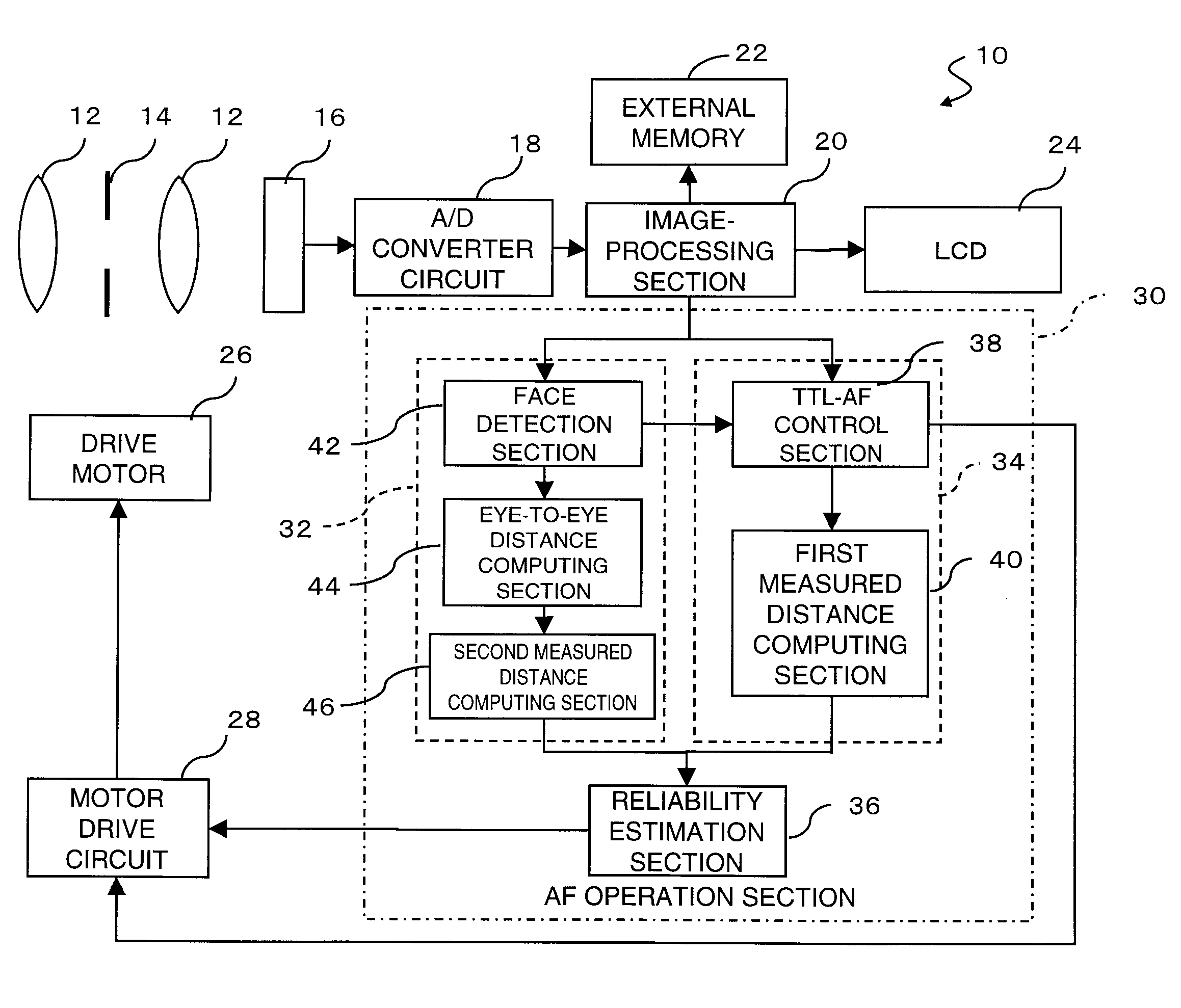
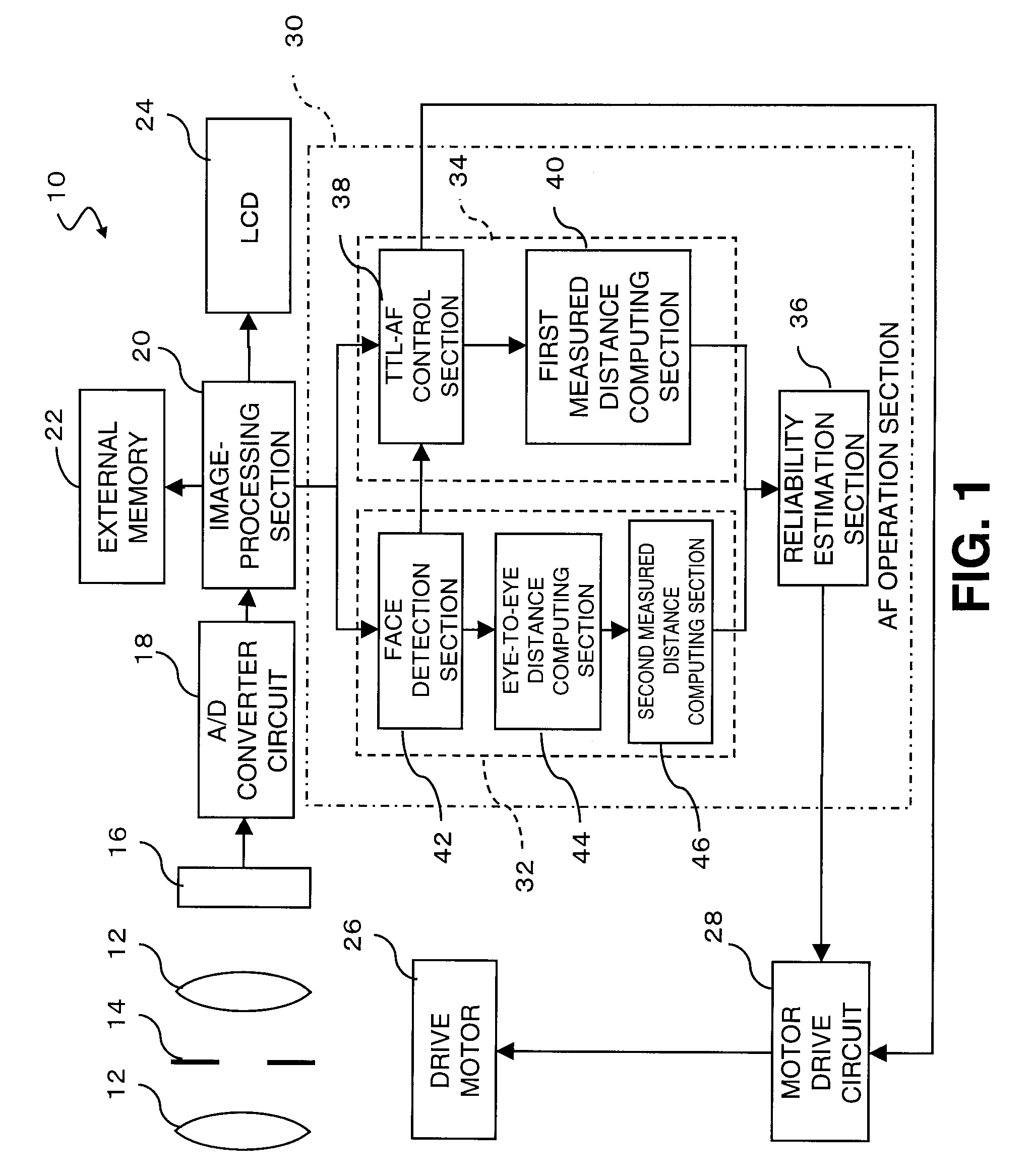
[0041]Embodiments of the present invention will be described hereinbelow by reference to the drawings. FIG. 1 is a block diagram showing the general configuration of a digital camera 10 corresponding to an embodiment of the present embodiment.

[0042]Luminous flux of a subject condensed by a group of lenses 12 and an aperture member 14 is subjected to photoelectric conversion performed by a CCD 16 serving as an imaging element, and the thus-converted flux is converted into a digital signal by an analog-to-digital converter circuit 18. A digital signal output from the analog-to-digital converter circuit 18 is input to an image-processing section 20. The image-processing section 20 subjects the input digital signal to predetermined image processing; e.g., pixel addition processing, color correction processing, and distortion correction processing, and the like; and outputs the processed signal as image data. Specifics of image processing are changed, as required, in accordance with the ...


PUM


Abstract

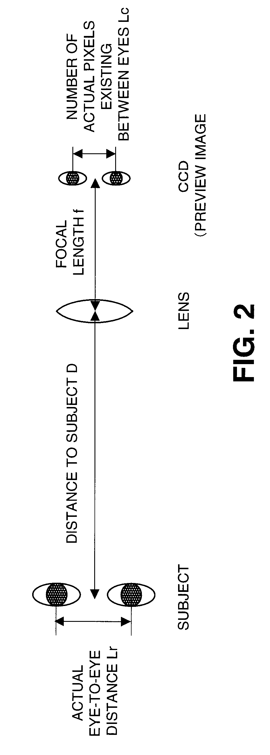
The accuracy of focus adjustment operation is enhanced further. When focus adjustment operation is performed, a first measured distance acquired by utilization of TTL-AF and a second measured value acquired by utilization of a distance between the eyes have been computed in advance. The degree of reliability of the first measured distance is compared the degree of reliability of the second measured distance in accordance with a result of a determination as to whether or not a face is detected (S10), a result of a determination as to whether or not an ambient brightness value Br is equal to or less than a reference value (S12), a result of a determination as to whether or not a focal length “f” is equal to or less than a reference value (S16), and a result of a determination as to whether or not a second measured distance De is less than a first measured distance Dt (S18). Focus adjustment operation is performed in accordance with a measured distance determined to be more reliable.

Description

CROSS REFERENCE TO RELATED APPLICATIONS[0001]This application claims priority to Japanese Patent Application No. 2006-229413 filed on Aug. 25, 2006, which is incorporated herein by reference in its entirety.FIELD OF THE INVENTION[0002]The present invention relates to an imaging apparatus which adjusts a focus by means of adjusting the position of a group of focus adjustment system lenses included in an imaging optical system.BACKGROUND OF THE INVENTION[0003]Many pieces of imaging apparatus currently on the market have an autofocus (hereinafter abbreviated as “AF”) for automatically adjusting a focus. A technique called TTL-AF (through-the-lens AF) is heavily used for this AF function at the present time. TTL-AF is a technique utilizing the fact that the edge of an image of the subject becomes clear at a focused focal point. Specifically, according to this technique, a specific frequency component of a predetermined area in a captured image (a preview image) is extracted, and an eval...

Claims


Application Information

Patent Timeline
Patent Type & Authority Applications(United States)
IPC IPC(8): G03B13/00G03B3/00
CPCG02B7/36G02B27/0093G03B3/00H04N5/23219G03B2213/02H04N5/23212G03B13/36H04N23/673H04N23/61H04N23/611
Inventor MIZUTANI, NAOKIKANAI, KUNIHIKOSHIBATA, YUJIHARADA, MASAO
Owner MONUMENT PEAK VENTURES LLC
Learn More