
Non-invasive acquisition of large nerve action potentials (NAPs) with closely spaced surface electrodes and reduced stimulus artifacts

a nerve action potential and naps technology, applied in the field of naps, can solve the problems of affecting the usefulness of the detected signal, and the system is susceptible to stimulus artifacts, so as to achieve the effect of effectively minimizing or substantially eliminating stimulus artifacts

Inactive Publication Date: 2008-02-28
NEUROMETRIX
View PDF0 Cites 137 Cited by
  • Summary
  • Abstract
  • Description
  • Claims
  • Application Information

AI Technical Summary

Benefits of technology

[0017] The present invention addresses the foregoing problems associated with the prior art by providing a novel method and apparatus for, non-invasively detecting large nerve action potentials (NAPs) while effectively minimizing or substantially eliminating stimulus artifacts, even where the stimulation site and the detection site are in close physical proximity to one another, e.g., within about 2 cm of one another.

Problems solved by technology

One problem with the system of the aforementioned U.S. Pat. Nos. 5,284,153 and 5,284,154 is that the system is susceptible to contamination by stimulus artifacts.
However, if the detector's surface electrodes are placed close to the stimulation site so as to yield a higher intensity nerve action potential (NAP), the stimulus artifacts can be substantial relative to the nerve signal itself.
These large stimulus artifact displacements can interfere with the relatively modest amplitudes of the nerve action potentials (NAPs) obtained by the detector's surface electrodes thereby undermining the usefulness of the detected signal (i.e., the trace).
This may not always be possible or convenient, depending upon the specific nerve which is being studied and / or on variations in patient anatomy, etc.
However, even using biphasic stimulation with a recording amplifier having a high pass filter with a relatively low cut-off frequency does not eliminate stimulus artifacts when the separation distance between the stimulation site and the detection site is small.
Such a separation distance may still be too large for many applications.
However, this approach is generally not preferred, since it is a highly invasive approach.

Method used


Image

  • Non-invasive acquisition of large nerve action potentials (NAPs) with closely spaced surface electrodes and reduced stimulus artifacts
  • Non-invasive acquisition of large nerve action potentials (NAPs) with closely spaced surface electrodes and reduced stimulus artifacts
  • Non-invasive acquisition of large nerve action potentials (NAPs) with closely spaced surface electrodes and reduced stimulus artifacts

Examples


Embodiment Construction

Reducing Stimulus Artifacts by Shorting the Stimulator's Anode and Cathode

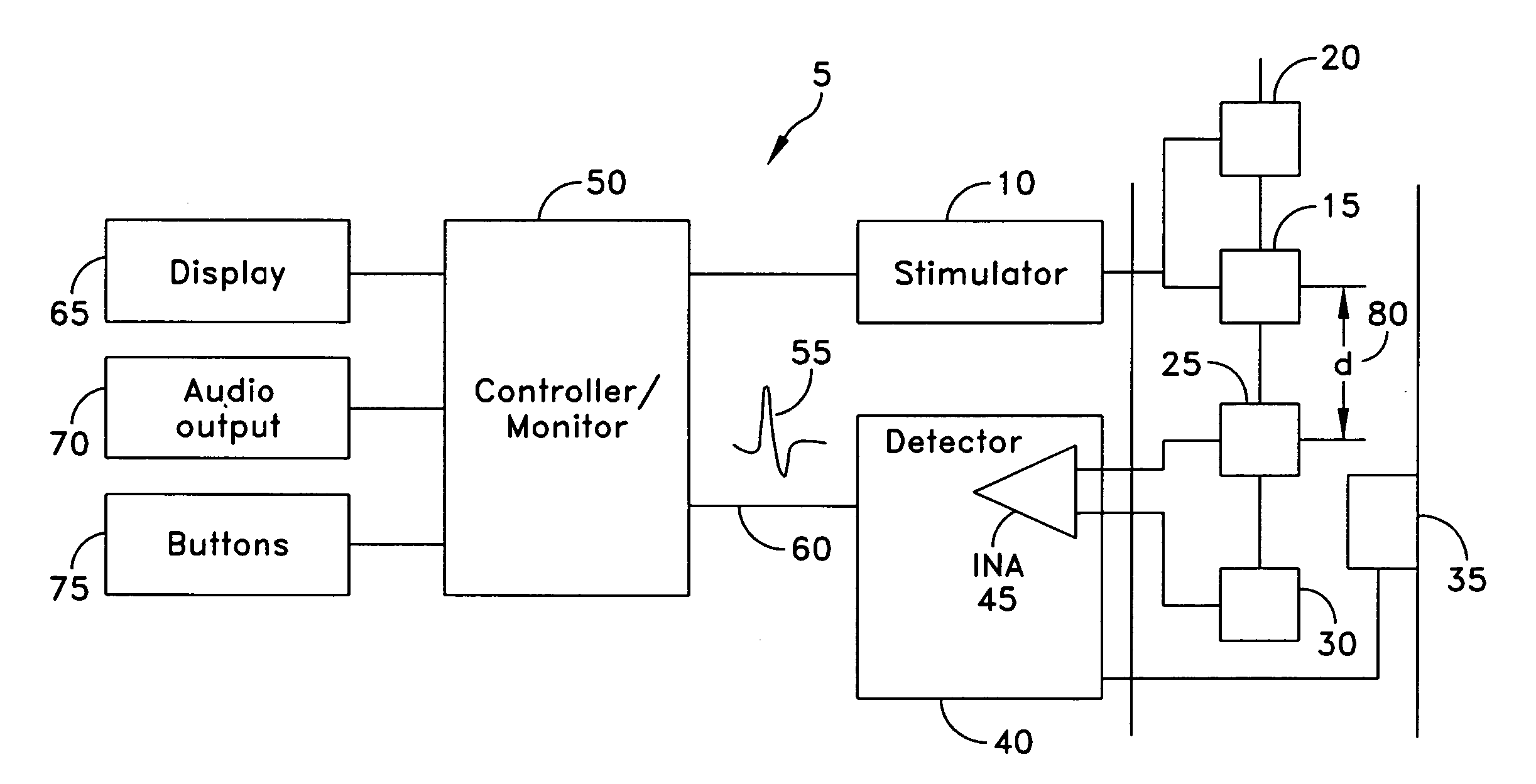
[0079] Looking first at FIG. 1, there is shown a device 5 which comprises a preferred embodiment of the present invention. More particularly, device 5 comprises apparatus for, non-invasively detecting large nerve action potentials (NAPs) while effectively minimizing or substantially eliminating stimulus artifacts, even where the stimulation site and the detection site are in close physical proximity to one another, e.g., within about 2 cm of one another.

[0080] NAP acquisition device 5 comprises a constant current stimulator circuit (also known as the stimulator) 10 that delivers an electrical stimulus to the stimulating electrodes 15 and 20 so as to stimulate a nerve of a patient. The evoked nerve action potential (NAP) is detected by a pair of surface electrodes 25 and 30, preferably in conjunction with a reference surface electrode 35. Electrodes 25 and 30 (and preferably also 35) are connected to a detect...


PUM


Abstract

The present invention addresses the foregoing problems associated with the prior art by providing a novel method and apparatus for, non-invasively detecting large nerve action potentials (NAPs) while effectively minimizing or substantially eliminating stimulus artifacts, even where the stimulation site and the detection site are in close physical proximity to one another, e.g., within about 2 cm of one another.

Description

REFERENCE TO PENDING PRIOR PATENT APPLICATIONS [0001] This patent application claims benefit of: [0002] (i) pending prior U.S. Provisional Patent Application Ser. No. 60 / 799,512, filed May 11, 2006 by Changwang Wu et al. for NON-INVASIVE ACQUISITION OF GIANT NERVE ACTION POTENTIALS (Attorney's Docket No. NEURO-16 PROV); and [0003] (ii) pending prior U.S. Provisional Patent Application Ser. No. 60 / 875,292, filed Dec. 15, 2006 by Michael Williams et al. for NEUROLOGICAL DIAGNOSTIC AND THERAPEUTIC SYSTEM WITH WIRELESS FUNCTIONAL MODULES (Attorney's Docket No. NEURO-22 PROV). [0004] The two above-identified patent applications are hereby incorporated herein by reference. FIELD OF THE INVENTION [0005] This invention relates to methods and apparatus for electrically stimulating a nerve and for detecting the evoked nerve action potentials (NAPs), for both diagnostic and therapeutic purposes. BACKGROUND OF THE INVENTION [0006] U.S. Pat. Nos. 5,284,153 and 5,284,154 disclose a system for loc...

Claims


Application Information

Patent Timeline
IPC IPC(8): A61N1/04
CPCA61B5/04001A61N1/0456A61N1/0476A61B5/7217A61N1/08A61N1/36014A61N1/0492A61B5/4041A61N1/3603A61B5/24
Inventor WU, CHANGWANGGOZANI, SHAI
Owner NEUROMETRIX
Learn More