Guide Assembly

a technology of guide arms and assembly parts, applied in the field of guide arms, can solve the problems of the need to locate instruments in the intramedullary canal, and achieve the effects of reducing the cost of assembly, easy manufacturing, and increasing the distance between the reference arm and the locator arm

Active Publication Date: 2008-02-28
DUPUY INT LTD
View PDF10 Cites 45 Cited by
  • Summary
  • Abstract
  • Description
  • Claims
  • Application Information

AI Technical Summary

Benefits of technology

[0006] Accordingly, the mechanical axis of a bone can be determined accurately during surgery using the guide assembly of the present invention without the use of an intramedullary rod.
[0022] The guide assembly will generally be made from metallic based materials, which are conventionally used in the manufacture of surgical instruments. Certain stainless steels can be particularly preferred. However, it will be understood that at least one part of the assembly, for instance the reference arm, can be made from polymeric materials. Using polymeric materials can reduce the cost of manufacture of the assembly, especially because an assembly made from polymeric materials can easily be manufactured using a moulding process. Suitable polymeric materials include certain polycarbonates, polyester, polyamides, poly-ether-ether ketones (PEEKs), and polyaryl-ether ketones (PAEKs). Polymeric materials can be reinforced with particulate material, especially fibrous materials, to provide appropriate wear and reinforcement characteristics.

Problems solved by technology

A disadvantage of this technique is the requirement to locate an instrument in the intramedullary canal.

Method used


Image

  • Guide Assembly
  • Guide Assembly
  • Guide Assembly

Examples


Embodiment Construction

[0034] In the described embodiment the guide assembly of the invention is used to determine the mechanical axis of a femur. Nevertheless, it will be understood that the guide assembly can be used to determine the mechanical axis of other types of bone, such as the humerus.

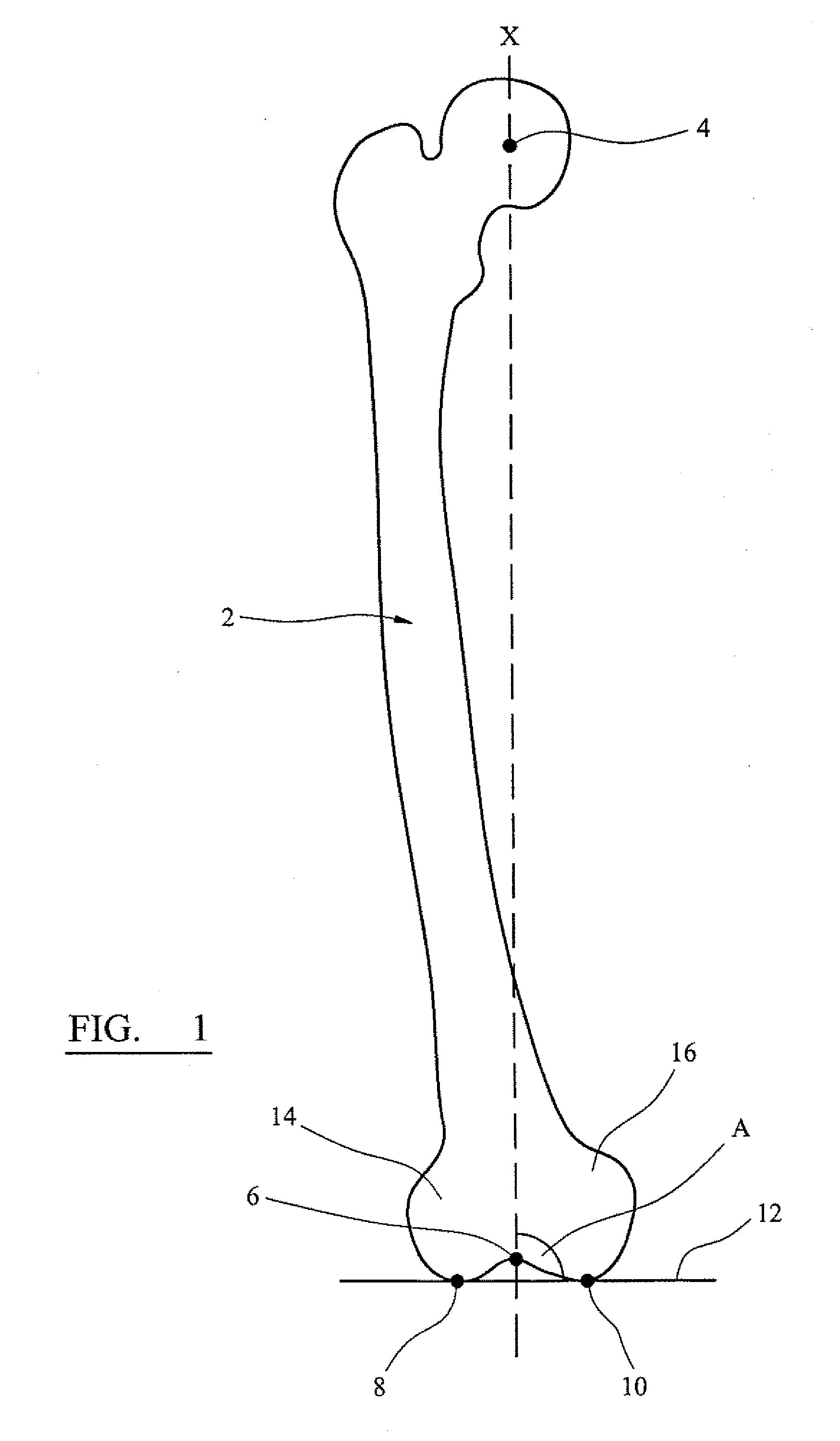
[0035] Referring to the drawings, FIG. 1 shows a femur 2 having a mechanical axis X. The mechanical axis X of the femur 2 is the line, which extends through the centre point 4 of the head of the femur and the centre point 6 of the intercondylar notch.

[0036] The angle A between the mechanical axis X and a reference axis 12 containing first 8 and second 10 reference points can be determined pre-operatively. In the described embodiment, the first 8 and second 10 reference points are the distal most points of the femurs first 14 and second 16 condyles. Nevertheless, as will be understood, this need not necessarily be the case and the reference points can be any other predetermined reference points on the femur 2. The...


PUM


Abstract

A method for locating the mechanical axis of a long bone involves generating an image of the long bone and determining the angle between the mechanical axis of the bone and a reference axis, which contains at least two reference points towards one end of the bone. A reference arm is positioned relative to the at least two predetermined reference points, and the mechanical axis is located relative to the reference arm with reference to the previously determined angle.

Description

BACKGROUND TO THE INVENTION [0001] The present invention relates to a guide assembly, and in particular a guide assembly for locating the mechanical axis of a bone. [0002] During surgery it is often necessary to locate the mechanical axis of a bone. For example, during knee surgery it is necessary to find the mechanical axis of the femur so that the femur can be appropriately resected in order to properly fit a femoral prosthesis. It is known to determine the angle between the anatomical and mechanical axes using pre-operative x-ray or other images. During the procedure, the anatomical axis can be determined using an intramedullary rod, which is located in the bone's intramedullary canal. The mechanical axis can then be determined with reference to the pre-operative image data and the intramedullary rod. A disadvantage of this technique is the requirement to locate an instrument in the intramedullary canal. SUMMARY OF THE INVENTION [0003] The present invention provides a technique f...

Claims


Application Information

Patent Timeline
Patent Type & Authority Applications(United States)
IPC IPC(8): A61B17/56
CPCA61B17/155A61B2019/467A61B2017/0268A61B17/1764A61B2090/067
Inventor COLQUHOUN, CALLUMFULTON, MARKROCK, MICK
Owner DUPUY INT LTD
Why Eureka
Try Eureka