Fatigue Crack Growth Curve Estimation Method, Estimation Program, And Estimation Device

a growth curve and growth curve technology, applied in the direction of force/torque/work measurement apparatus, instruments, using mechanical means, etc., can solve the problems of inability to obtain, damage to the structure being supposed to be safe, and severe use environment of steel structur

Inactive Publication Date: 2008-02-28
SANGAKU RENKEI KIKO KYUSHU KK
View PDF6 Cites 23 Cited by
  • Summary
  • Abstract
  • Description
  • Claims
  • Application Information

AI Technical Summary

Benefits of technology

[0031] (1) According to the present invention, assuming that the size of a fatigue damage accumulated region being a cyclic plastic zone determines crack propagation rate, it is possible to precisely estimate fatigue life of metal and the detailed behavior of the initiation and growth of a crack in accordance with a practical phenomenon in which the crack continuously grows in a sound area without the crack at all.
[0032] (2) According to the present invention, assuming that the size of the fatigue damage accumulated region determines the crack propagation rate and using the fatigue damage accumulated region enables physically clear management by which if the fatigue damage accumulated region does not occur, in other words, if plastic strain does not proceed, the crack does not propagate.
[0033] (3) According to the present invention, inside of a first grain at a notch root, the crack is a shear crack at first on which not only compressive stress but also tensile stress is transmitted. After the shear crack exceeds a first grain boundary, dislocation shifts to a direction inclined from a slipband inside the first grain, so that plastic strain is accumulated in a direction perpendicular to a slip by a cyclic load inside the first grain. It is assumed that a position where this accumulated plastic strain reaches a ductility limit specific to a material is changed into an opening mode crack on which the tensile stress is not transmitted, so that it is possible to reproduce a practical behavior in which the shear crack is gradually changed into the opening crack.
[0034] (4) According to the present invention, the inherent displacement formed ahead of the crack differs according to a load level, and the inherent displacement taken at a load level of generating the crack differs too. Thus, it is possible to analytically give the same load as the re-tensile plastic zone's generated load obtained by experiments by comparing the multiple of the difference between crack opening displacement at the minimum load and crack opening displacement in a case where contact stress is not applied because a crack closing zone does not occur by a ratio determined as a function of the cumulative plastic strain with the crack opening displacement at the minimum load.
[0035] (5) According to the present invention, it is guaranteed that plastic grows in a second cycle or later too in an initial state in which the crack propagates in a shearing manner under constant load amplitude. At the same time, when load amplitude which is slightly larger than a fatigue limit is applied in a state that the crack stops to grow by passing many cycles immediately below a fatigue limit, the so-called coaxing effect by which the fatigue limit is apparently increased without propagating the crack is realized.
[0036] (6) It is possible to grow the crack at a time with considering that an upper limit for an increment of the crack which can advance at a time by calculation is 5% when a constant amplitude load continues for a while.

Problems solved by technology

With the development of industrial technology, demands for high efficiency, high performance, low cost, and safety have been further increased, and the usage environment of a steel structure has become severe.
However, there are often cases where a structure being supposed to be designed safely is damaged earlier than expected.
Fatigue design using the S-N curve is effective to some extent as an empirical rule being feedback on actual use, but information about the size of a crack and the like cannot be obtained and there are many cases where the fatigue design using the S-N curve is disabled in a new style structure.
In actual fact, however, the fatigue design only takes measures against individuals by reducing operating stress by increasing thickness and the like, and any fundamental treatment cannot be adopted.

Method used


Image

  • Fatigue Crack Growth Curve Estimation Method, Estimation Program, And Estimation Device
  • Fatigue Crack Growth Curve Estimation Method, Estimation Program, And Estimation Device
  • Fatigue Crack Growth Curve Estimation Method, Estimation Program, And Estimation Device

Examples


first embodiment

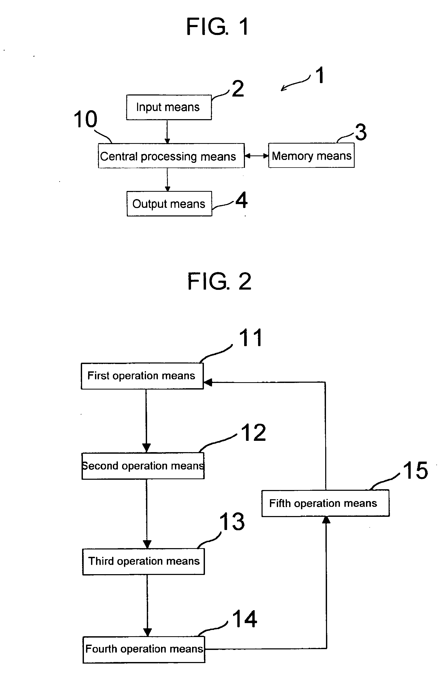
[0062]FIG. 1 shows an estimation device of a fatigue crack growth curve according to a first embodiment of the present invention.

[0063] The estimation device 1 of the fatigue crack growth curve includes input means 2, memory means 3, output means 4, and central processing means 10. The input means 2 is provided with, for example, a keyboard, a pointing device, or the like to input initial values of parameters necessary for operation. The input means 2 may read a file on which the initial values of the parameters necessary for operation are written to input them. The central processing means 10 includes a central processing unit of a computer or the like to carry out operation.

[0064] The memory means 3 temporarily stores values of parameters operated by the central processing means 10 on, for example, a hard disk, a memory of the computer, or the like. The output means 4 outputs the values of the parameters operated by the central processing means 10 to a recording medium. The outp...

second embodiment

[0147] In the first embodiment of the present invention, S(x) and smR(x) between divided points are assumed to be linearly changed by the first-order approximation. In the second embodiment of the present invention, the fatigue crack growth curve is estimated by using second-order approximation.

[0148] S(x) and smR(x) between the divided points are simplified as follows by the second-order approximation. [Equation⁢ ⁢39]S⁢ ⁢xi=ai⁢x2+bi⁢x+ciSmR⁢xi=amRi⁢x2+bmRi⁢x+cmRiwherein,⁢ai=1xi+2-xi+1⁢(Si+2-Sixi+2-xi-Si+1-Sixi+1-xi)bi=Si+2-Sixi+2-xi-xi+2-xixi+2-xi+1⁢(Si+2-Sixi+2-xi-Si+1-Sixi+1-xi)ci=Si+2-xi+22xi+2-xi+1⁢(Si+2-Sixi+2-xi-Si+1-Sixi+1-xi)-xi+2⁢{Si+2-Sixi+2-xi-xi+2-xixi+2-xi+1⁢(Si+2-Sixi+2-xi-Si+1-Sixi+1-xi)}(ditto⁢ ⁢for⁢ ⁢smR⁡(x)i)

Substituting equation (2) into equation (1), [Equation⁢ ⁢40] Pc⁢ ⁢max⁢∑i=1n⁢[ai⁢{(-xi⁢a2-xi2+a2⁢sin-1⁢xia)-(-xi-1⁢a2-xi-12+a2⁢sin-1⁢xi-1a)}+bi⁢a2-xi-1-a2-xi+ci⁡(sin-1⁢xia-sin-1⁢xi-1a)]+∑i=1n⁢ ⁢[am⁢ ⁢Ri⁢{(-xi⁢a2-xi2+a2⁢sin-1⁢xia)-(-xi-1⁢a2-xi-12+a2⁢sin-1⁢xi...


PUM

PropertyMeasurementUnit
crack lengthaaaaaaaaaa
stress intensity factoraaaaaaaaaa
residual stressaaaaaaaaaa

Abstract

There are provided a fatigue crack growth curve estimation method, an estimation program, and an estimation device capable of strictly estimating the detail of the metal fatigue end and the crack growth detail. The fatigue crack growth curve estimation device (1) uses a first calculation means (11), second calculation means (12), third calculation means (13), fourth calculation means (14), and fifth calculation means (15) to strictly estimate the detail of growth of a crack generated and growing in a first grain while omitting a calculation on the load pair not contributing to growth of the crack.

Description

TECHNICAL FIELD [0001] The present invention relates to an estimation method, an estimation program, and an estimation device for quantitatively estimating a fatigue crack initiation and growth curve at a stress concentrated area in a steel structure being a polycrystal. BACKGROUND ART [0002] With the development of industrial technology, demands for high efficiency, high performance, low cost, and safety have been further increased, and the usage environment of a steel structure has become severe. Thus, a design engineer is desired to rationally design a structure from mutually contradictory standpoints of high performance, economically efficiency, and safety. [0003] However, there are often cases where a structure being supposed to be designed safely is damaged earlier than expected. In the case of a steel structure, it is said recently that “fatigue” directly or indirectly causes 80% or more of the damage as a result of dramatically improving the performance of a material. [0004]...

Claims


Application Information

Patent Timeline
Patent Type & Authority Applications(United States)
IPC IPC(8): G01B21/30G01L1/00
CPCG01N3/32G01N2203/0066G01N2203/0064
Inventor TOYOSADA, MASAHIRO
Owner SANGAKU RENKEI KIKO KYUSHU KK
Why Eureka
Try Eureka