Method and apparatus for monitoring an optical network signal

a technology of optical network and monitoring method, applied in the direction of optical transmission, electromagnetic transmission, instruments, etc., can solve the problems of loss of communication signal at terminating apparatus, inability to be an intelligent device to monitor signal at customer premises, and limited visibility of network and its operation sta

Inactive Publication Date: 2008-02-28
SBC KNOWLEDGE VENTURES LP
View PDF10 Cites 15 Cited by
  • Summary
  • Abstract
  • Description
  • Claims
  • Application Information

AI Technical Summary

Problems solved by technology

This implies that there would not be an intelligent device to monitor the signal at the customer premises (from the SP's perspective) because there is typically no intelligent network monitoring equipment located at the CPE location.
In the absence of intelligent network monitoring equipment, visibility of the network and assessment of its operation state is limited to the network monitoring elements located in the Central Office (CO).
Even if the original signal were provisioned over a diverse (physical separation) pair of fiber, a fiber cut on the signal path of the communication signal will result in loss of the communication signal at the terminating apparatus.
Without a test signal from the CO, the terminating will be unable to provide feedback (other than “no signal present on the fiber”) to the CO.
Inability to determine where faults occur may result in increased costs for personnel servicing dispatches and expending troubleshooting time.
A switched optical conversion and analysis device including optical switches at customer sites is costly and requires significant equipment expense at the customer site.

Method used


Image

  • Method and apparatus for monitoring an optical network signal
  • Method and apparatus for monitoring an optical network signal
  • Method and apparatus for monitoring an optical network signal

Examples


Embodiment Construction

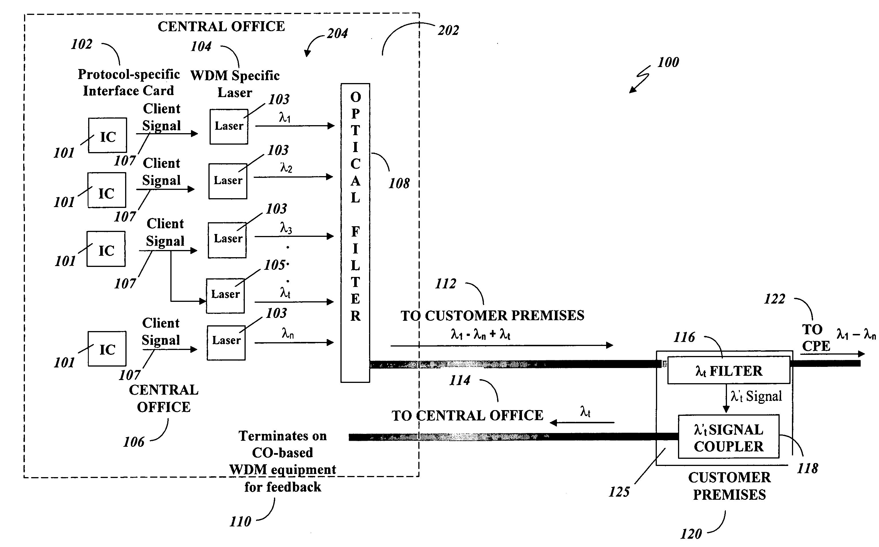
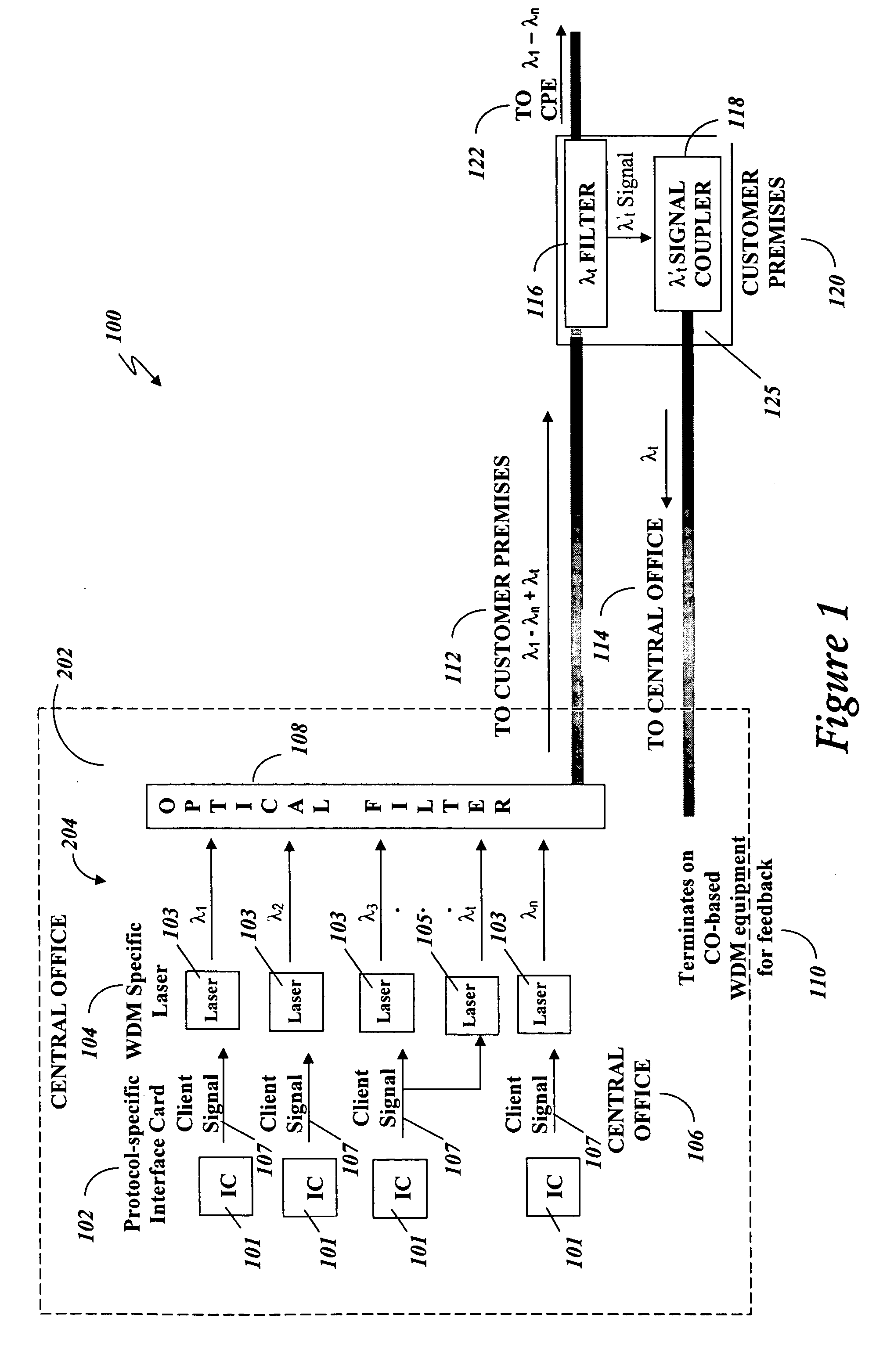
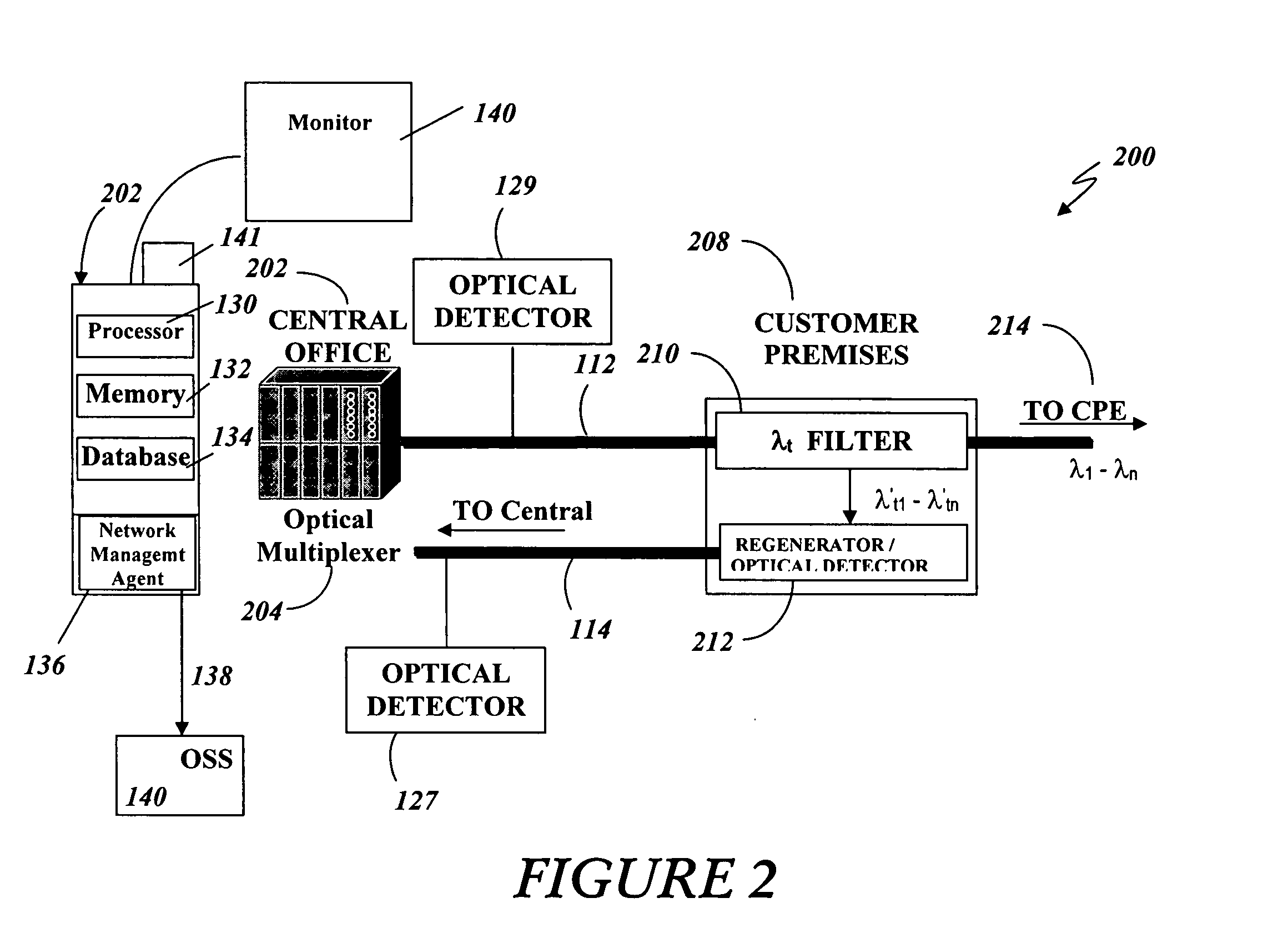
[0009]In an illustrative embodiment, a method for monitoring a communication link between a first apparatus and a second apparatus is disclosed, the method including modulating at the first apparatus a client signal to generate a communication signal at a communication wavelength, λ1; modulating at the first apparatus, the client signal to generate a test signal at a test wavelength, λt; sending the test signal and the communication signal concurrently on an optical fiber from the first apparatus to the second apparatus for permanently separating the test signal from the communication signal at the second apparatus; and receiving at the first apparatus on a return path of the communication link from the second apparatus a signal indicating whether the test signal was received at the second apparatus.

[0010]In another particular embodiment the test signal is separated passively from the communication signal at the second apparatus and returned to the first apparatus. In another partic...


PUM


Abstract

A method is disclosed for monitoring a communication link between a first apparatus and a second apparatus, the method comprising receiving concurrently from the first apparatus (e.g., a central office) at the second apparatus (e.g., an optical demarcation point at a customer premises) a communication signal at a communication wavelength, λ1 and a test signal at a test wavelength λt, permanently separating the test signal from the communication signal at the second apparatus and sending to the first apparatus on a return path between the first apparatus and the second apparatus a signal indicating whether the test signal was received at the second apparatus. An apparatus is disclosed including an interface for receiving concurrently the communication signal and the test signal, a filter for permanently separating the test signal from the communication signal and a coupler for permanently placing a signal on a return path.

Description

FIELD OF THE DISCLOSURE[0001]The present disclosure relates to monitoring an optical signal on a communication link.BACKGROUND[0002]Dense Wavelength Division Multiplexing (DWDM) is a technology that transmits multiple data signals using different wavelengths of light through a single optical fiber. Incoming optical signals are assigned to specific frequencies within a designated frequency band. The capacity of the optical fiber is increased when these signals are multiplexed out onto the fiber.[0003]DWDM is protocol and bit rate independent so data signals using varying protocols such as asynchronous transfer mode (ATM), SONET, and internet protocol (IP) can be transmitted through the same data stream over a single optical fiber pair regardless of their speed and protocol differences. Each individual protocol remains intact during the transmission process because there is not an optic-electric-optic conversion during transmission with DWDM transmission. The fact that the signals are...

Claims


Application Information

Patent Timeline
Patent Type & Authority Applications(United States)
IPC IPC(8): G01R31/28
CPCH04B2210/078H04B10/0773
Inventor MATTESON, PATRICIA R.PASCASIO, JOREY M.PASCASIO, RENNE G.
Owner SBC KNOWLEDGE VENTURES LP
Why Eureka
Try Eureka