Contact switch

a technology of contact switch and switch body, which is applied in the direction of contact switch, high-tension/heavy-dress switch, air-break switch, etc., can solve the problem of unavoidable use of switch body in locations, and achieve the effect of simple structur

Active Publication Date: 2008-03-06
PANASONIC CORP
View PDF3 Cites 3 Cited by
  • Summary
  • Abstract
  • Description
  • Claims
  • Application Information

AI Technical Summary

Benefits of technology

[0006]The switch has a simple structure and connects between the contacts reliably.

Problems solved by technology

Thus, the switch is used in locations unavoidable from dusts, moisture, and gases.

Method used


Image

  • Contact switch
  • Contact switch
  • Contact switch

Examples


Embodiment Construction

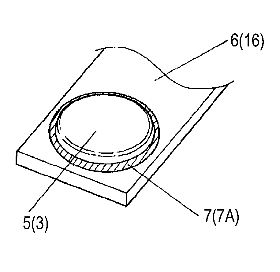
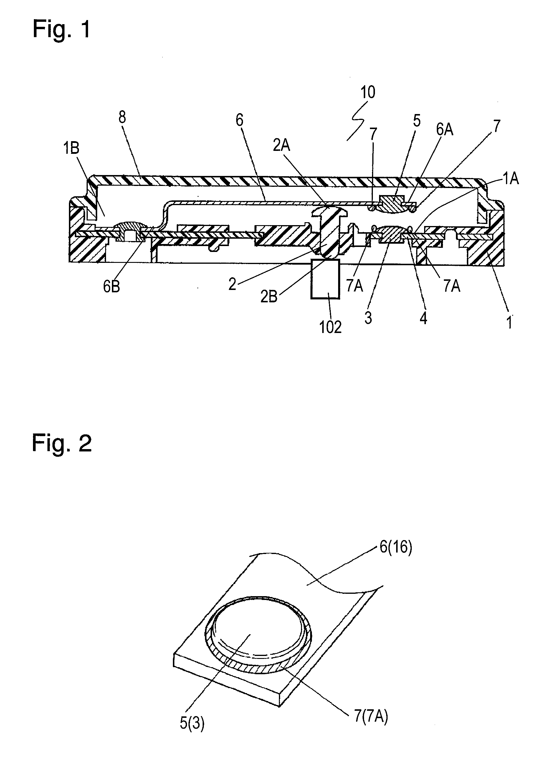
[0013]FIG. 1 is a cross sectional view of a contact switch 10 according to an exemplary embodiment for turning on and off a lamp, such as turn signal lamps and brake lamps. The switch 10 includes a case 1 made of insulating resin and an actuator 2 made of insulating resin. The case 1 has substantially a box shape. The actuator 2 has substantially a cylindrical shape. The case 1 has a recess 1B provided therein. The recess 1B has a bottom 1A. Second strips 4, fixed strips, are embedded in the bottom 1A of the case 1. Second strips 4 have second contacts 3, fixed contacts, mounted thereto, respectively. Each second contact 3 has a rivet shape made of metal, such as silver or copper apply. The second contacts 3 expose from the bottom 1A. Actuator 2 is accommodated in the recess 1B movably upward and downward.

[0014]A first contact 5, a movable contact, has a rivet shape made of metal, such as silver or copper alloy, and is fixed to end 6A of first strip 6, a movable strip, made of a thi...


PUM


Abstract

A contact switch includes a case, a first contact provided in the case, a second contact provided in the case, an actuator for causing the first contact to contact the second contact, and an oil-repellent agent applied to at least one of an outer edge of the first contact or an outer edge of the second contact The oil-repellent agent includes a fluorine-based polymer. The switch has a simple structure and connects between the contacts reliably.

Description

FIELD OF THE INVENTION[0001]The present invention relates to a contact switch including contacts, for use in an environment, such as automobiles, where oil, such as lubricant oil, exists.BACKGROUND OF THE INVENTION[0002]Various contact switches including contacts are used for turning on and off turn signal lamps for indicating directions of turn, stop lamps activated by a brake pedal, room lamps activated by a door.[0003]A conventional contact switch includes a case and an actuator accommodated movably in the case. The actuator moves according to operations of a lever and a brake pedal or opening / closing of a door, and connects and disconnects between a movable contact and a fixed contact which have rivet shapes and face each other for turning on and off a lamp.[0004]The contact switch is generally located near mechanisms, such as a steering assembly, a brake pedal, or doors, to which lubricants, such as grease or oil, are applied. Thus, the switch is used in locations unavoidable f...

Claims


Application Information

Patent Timeline
Patent Type & Authority Applications(United States)
IPC IPC(8): H01H9/00
CPCH01H13/18H01H3/16
Inventor KAIDA, SATOSHIMATSUI, TAKAONAWATE, HIROTAKA
Owner PANASONIC CORP
Why Eureka
Try Eureka