Container holder

a technology for containers and holder plates, applied in the field of containers, can solve the problems of increasing manufacturing costs, and achieve the effects of less manufacturing costs, less manufacturing costs, and high accuracy of disposing movable switching units and fixed switching units

Inactive Publication Date: 2008-03-06
TOYODA GOSEI CO LTD
View PDF5 Cites 18 Cited by
  • Summary
  • Abstract
  • Description
  • Claims
  • Application Information

AI Technical Summary

Benefits of technology

[0024]As described above, the present container holder can move the supporting member with an electromagnetic force, which arises in the second actuating unit of the actuator, that is, around the electromagnet of the second actuating unit. Hence, the present container holder does not require such an expensive device as electric motors at all. To put it differently, not only the present container holder can accommodate or hold containers with various shapes stably without using an electric motor, but also it can be manufactured less expensively.
[0025]In the present container holder which is provided with the first desirable arrangement (1), the holder body has a bottom. The bottom is disposed movably in an up / down direction, and at least a part of the bottom is disposed in the accommodation space. Moreover, in the present container holder which is provided with the first desirable arrangement (1), the switch has a movable switching unit and a fixed switching unit. The movable switching unit is fixed to the bottom of the holder body, and the fixed switching unit is fixed to the holder body. Since the bottom of the holder body is disposed movably in an up / down direction, and since at least a part of the bottom is disposed in the accommodation space, the bottom can move downward when a user accommodates or holds a container in the accommodation space. The downwardly moving bottom makes the movable switching unit approach the fixed switching unit. Accordingly, the switch turns on the second actuating unit of the actuator. On the other hand, when a user removes the container from out of the accommodation space, the bottom moves upward to separate the movable switching unit from the fixed switching unit. Consequently, the switch turns off the second actuating unit of the actuator. Therefore, in the present container holder which is provided with the first desirable arrangement (1), it is possible for a user to actuate the supporting member by simply putting a container into or taking it out of the accommodation space. Thus, the present container holder which is provided with the first desirable arrangement (1) does not at all require a user to carry out the complicated operations for actuating the supporting member.
[0026]In the present container holder which is provided with the second desirable arrangement (2), one of the movable switching unit and fixed switching unit of the switch comprises a magnet, and the other one of the movable switching unit and fixed switching unit of the switch comprises a Hall-effect switch. Due to the galvanomagnetic effect (or the Hall effect), a Hall element, which makes the Hall-effect switch, outputs an electric current when it is placed in a magnetic field with a predetermined strength or more. The Hall-effect switch utilizes the action of a Hall element to turn on the second actuating unit of the actuator, when it approaches the magnet, or vise versa. Moreover, the Hall-effect switch utilizes the action of a Hall element to turn off the second actuating unit of the actuator, when it gets away from the magnet, or vise versa. Accordingly, in the present container holder which is provided with the second desirable arrangement (2) in which the switch comprises the thus combined magnet and Hall-effect switch, the movable switching unit and the fixed switching unit do not necessarily contact with each other. Consequently, it is not required at all to dispose the movable switching unit and the fixed switching unit highly accurately. Therefore, the present container holder which is provided with the second desirable arrangement (2) can be manufactured much less expensively.
[0027]In the present container holder which is provided with the third desirable arrangement (3), it is possible to make the space smaller, space which is needed for disposing the supporting member, the actuator and the spacer. As a result, the present container holder which is provided with the third desirable arrangement (3) can not only be manufactured less expensively, can but also be suitably disposed in a limited space such as within automotive passenger rooms. Moreover, since the present container holder which is provided with the third desirable arrangement (3) further comprises the spacer being disposed as described above, it is possible to operate the supporting member with enhanced reliability.

Problems solved by technology

However, the conventional container holder has been associated with the problem that the manufacturing costs have gone up, because electric motors are expensive.

Method used


Image

  • Container holder
  • Container holder
  • Container holder

Examples


examples

[0040]The present container holder will be hereinafter described with reference to specific examples.

example no.1

Example No. 1

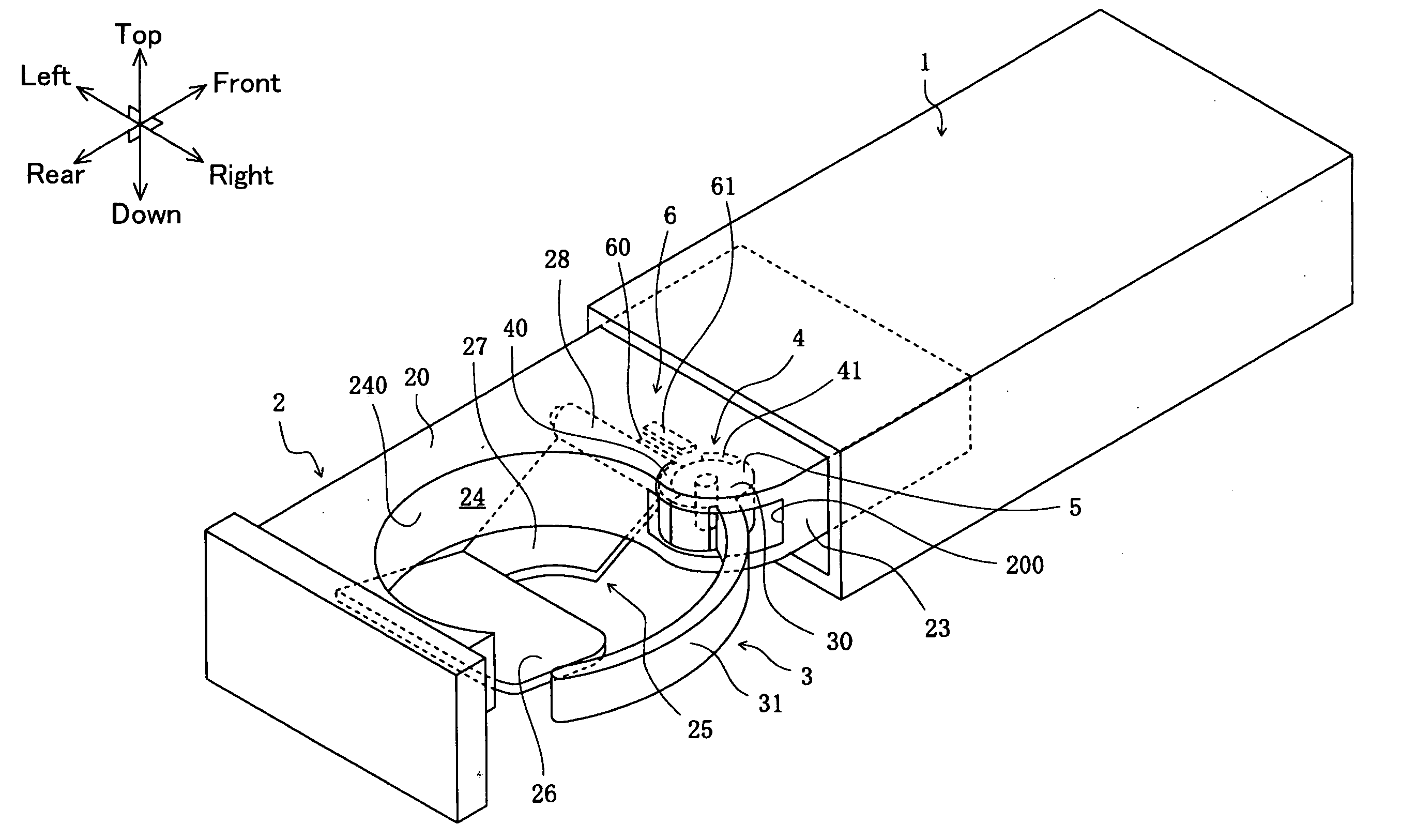
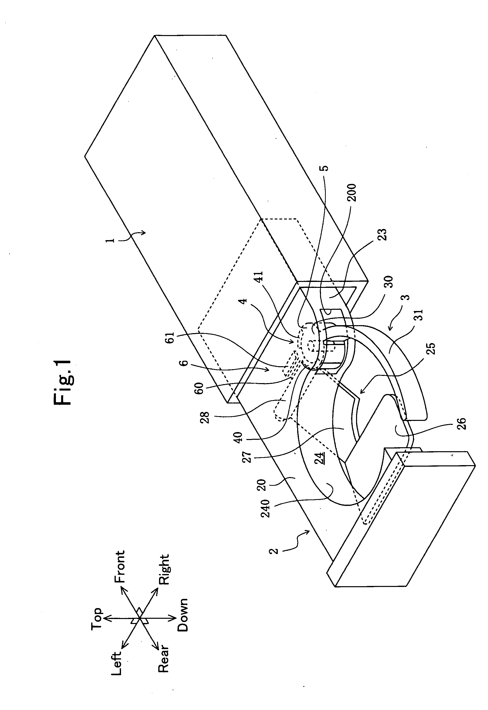
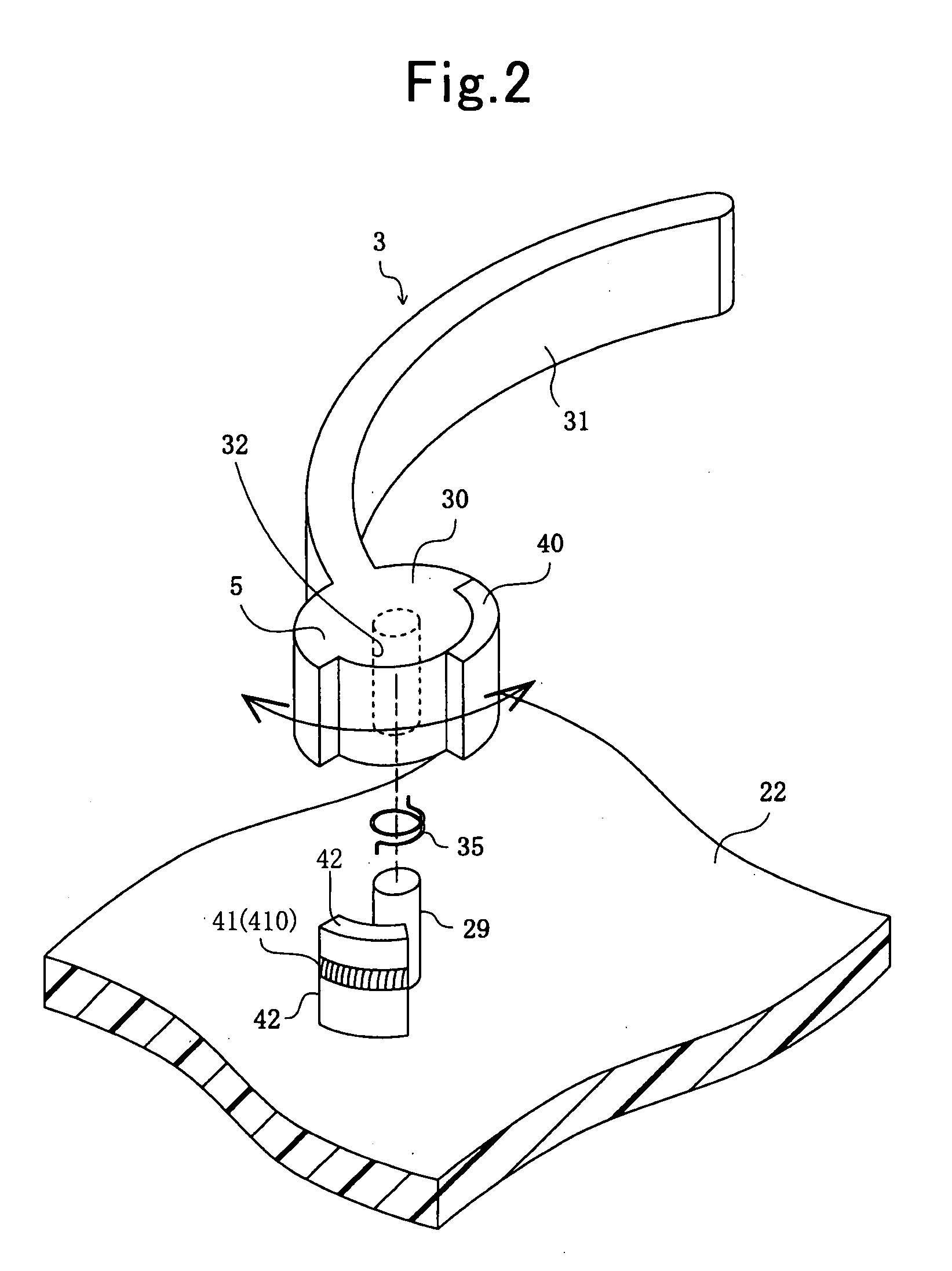
[0041]A container holder according to Example No. 1 of the present invention is an on-vehicle container holder, and is attached to an automotive instrument panel. FIG. 1 schematically illustrates the container holder according to Example No. 1 in a perspective diagram. FIG. 2 schematically illustrates the appearance of a supporting member and an actuator, which make the container holder according to Example No. 1, in a perspective diagram when they are viewed on the front side in FIG. 1. FIGS. 3 and 4 schematically illustrate how a bottom operates, bottom which makes the container holder according to Example No. 1, in a cross-sectional diagram, respectively. FIGS. 5 through 7 schematically illustrate the operations of the container holder according to Example No. 1 in an explanatory diagram, respectively. FIG. 8 schematically illustrates the operations of the switch, actuator, supporting member and spacer, which make the container holder according to Example No. 1, in a...

example no.2

Example No. 2

[0065]Except the following features, a container holder according to Example No. 2 of the present invention comprises the same component parts as those of the container holder according to Example No. 1. That is, the actuator 4's first actuating unit 40 is being magnetized. Moreover, the first actuating unit 40 is disposed at the location where the spacer 5 is disposed in the container holder according to Example No. 1. In addition, the spacer 5 is disposed at the location where the first actuating unit 40 is disposed in the container holder according to Example No. 1. FIGS. 9 and 10 schematically illustrate how the container holder according to Example No. 2 functions to operate the supporting member 3, the actuator 4, the spacer 5, and the switch 6.

[0066]In the container holder according to Example No. 2 of the present invention, the actuator 4's first actuating unit 40 comprises a magnet, a ferromagnet which is magnetized. The actuator 4's second actuating unit 41 co...


PUM


Abstract

A container holder includes a holder body, a supporting member, an actuator, and a switch. The supporting member is disposed movably to the holder body. The holder body demarcates an accommodation space for accommodating or holding a container therein partially. The actuator includes a first actuating unit, being made of a ferromagnet, and a second actuating unit, being made of an electromagnet. Moreover, one of the actuator's first actuating unit and second actuating unit is fixed to the holder body, and the other one of the actuator's first actuating unit and second actuating unit is fixed to the supporting member. The switch turns on and off the actuator's second actuating unit to have the electromagnet produce and lose an electromagnetic force. The resulting electromagnetic force moves the supporting member to come in and/or come out of the holder body's accommodation space.

Description

BACKGROUND OF THE INVENTION[0001]1. Field of the Invention[0002]The present invention relates to a container holder for accommodating or holding containers therein, containers which contain beverages.[0003]2. Description of the Related Art[0004]A container holder is an apparatus, which has an accommodation space for accommodating or holding containers, such as cans, plastic bottles and cups, therein, containers which hold beverages. As disclosed in Japanese Unexamined Patent Publication (KOKAI) No. 2005-329824, Japanese Unexamined Patent Publication (KOKAI) No. 2006-130968 and Japanese Unexamined Patent Publication (KOKAI) No. 2003-182438, for instance, conventional container holders have been known. Such a conventional container holder comprises a holder body, and a supporting member. The holder body demarcates at least a part of the accommodation space. The supporting member enlarges and diminishes the accommodation space diametrically.[0005]Usually, in this type of conventional c...

Claims


Application Information

Patent Timeline
Patent Type & Authority Applications(United States)
IPC IPC(8): B65D25/00
CPCB60N3/106B60N3/102Y10S224/926
Inventor YAMAMOTO, AYASAKAKIBARA, YASUHIRO
Owner TOYODA GOSEI CO LTD
Why Eureka
Try Eureka