

Permenent magnet rotating machine
a permanent magnet and rotating machine technology, applied in the direction of magnetic circuit rotating parts, magnetic body, magnetic circuit shape/form/construction, etc., can solve the problems of increasing coercive force at the end portions of permanent magnets, unsusceptibility, etc., to achieve high coercive force, increase coercive force, and high remanence
Active Publication Date: 2008-03-06
SHIN ETSU CHEM IND CO LTD
View PDF8 Cites 67 Cited by
- Summary
- Abstract
- Description
- Claims
- Application Information
AI Technical Summary
Benefits of technology
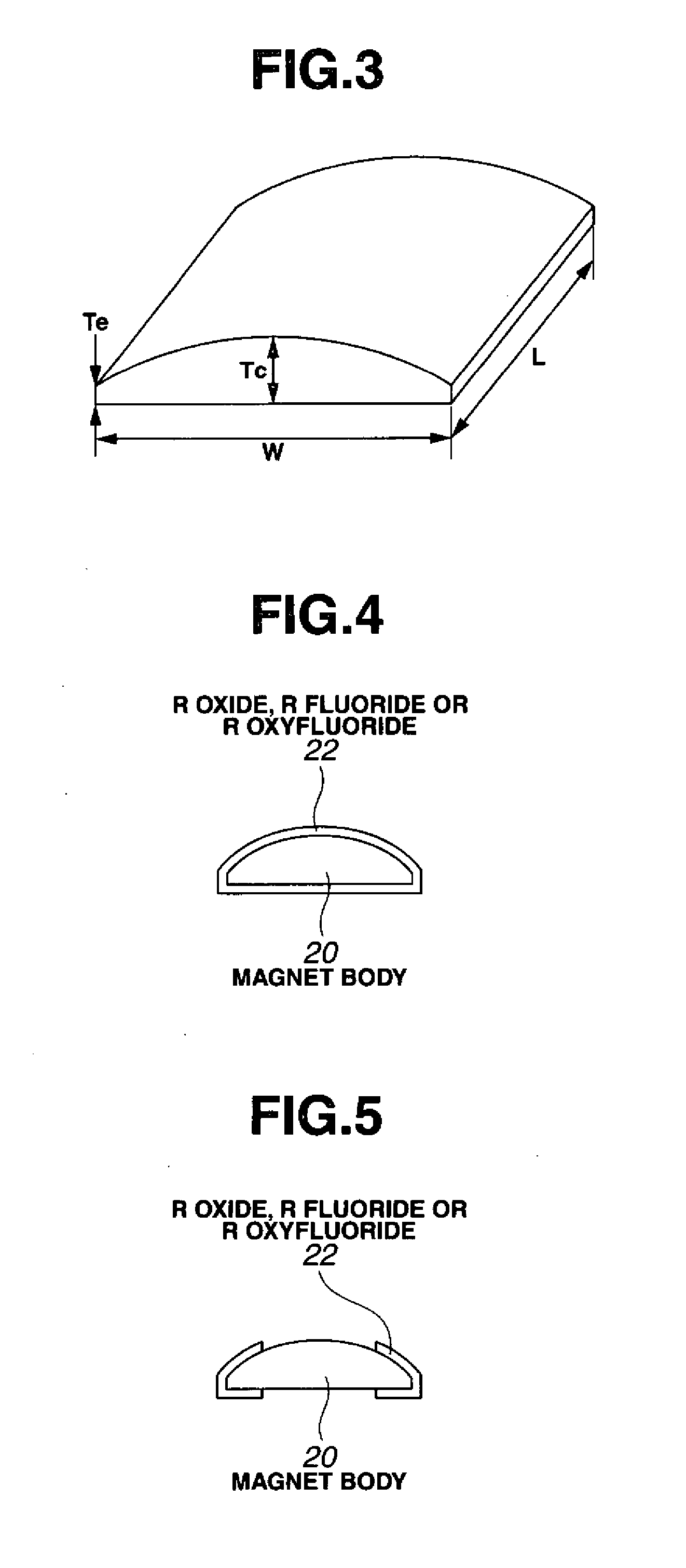
[0015] The inventors have found that when a R1—Fe—B sintered magnet, typically a Nd—Fe—B sintered magnet, on which surface is disposed a powder comprising one or more of an oxide of R2, a fluoride of R3 and an oxyfluoride of R4, is heated, R2, R3 or R4 contained in the powder is absorbed in the magnet body (wherein each of R1 to R4 is one or more elements selected from rare earth elements inclusive of Y and Sc) so that the coercive force is increased while substantially suppressing a decline of remanence. Particularly when a fluoride of R3 or an oxyfluoride of R4 is used, both R3 or R4 and fluorine are effectively absorbed in the magnet body so that a sintered magnet having a high remanence and a high coercive force is obtainable.
Problems solved by technology
More specifically, the permanent magnet has an increased coercive force at end portions thereof and is unsusceptible to demagnetization even at elevated temperature.
Method used
View moreImage
Smart ImageViewing Examples

Examples
example
[0060] Examples are given below for further illustrating the invention although the invention is not limited thereto. In Examples, the filling factor (or percent occupancy) of the magnet surface-surrounding space with powder like dysprosium oxide or dysprosium fluoride is calculated from a weight gain of the magnet after powder deposition and the true density of powder material.
Login to View More PUM
| Property | Measurement | Unit |
|---|---|---|
| particle size | aaaaa | aaaaa |
| volume fraction | aaaaa | aaaaa |
| size | aaaaa | aaaaa |
Abstract
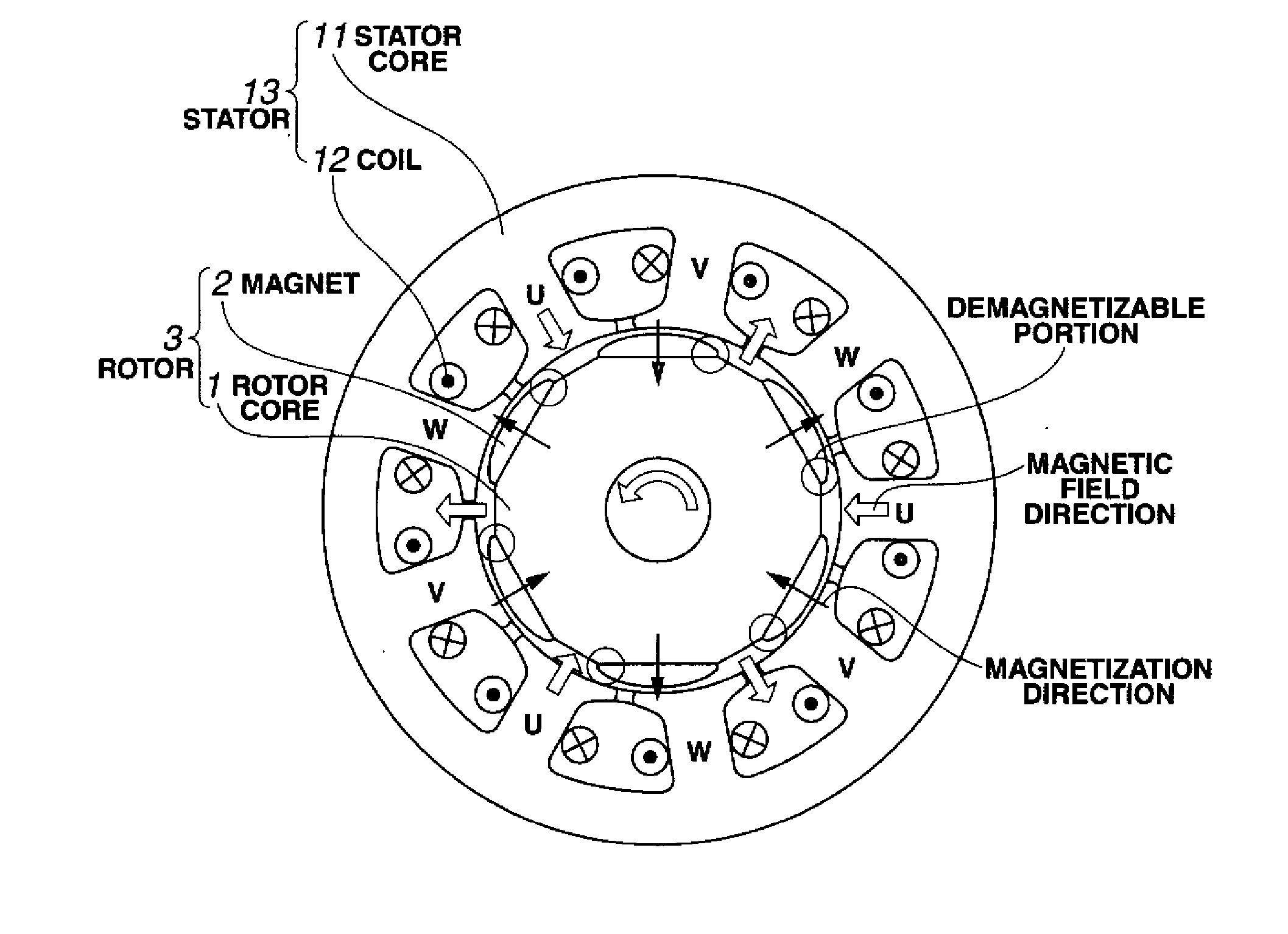
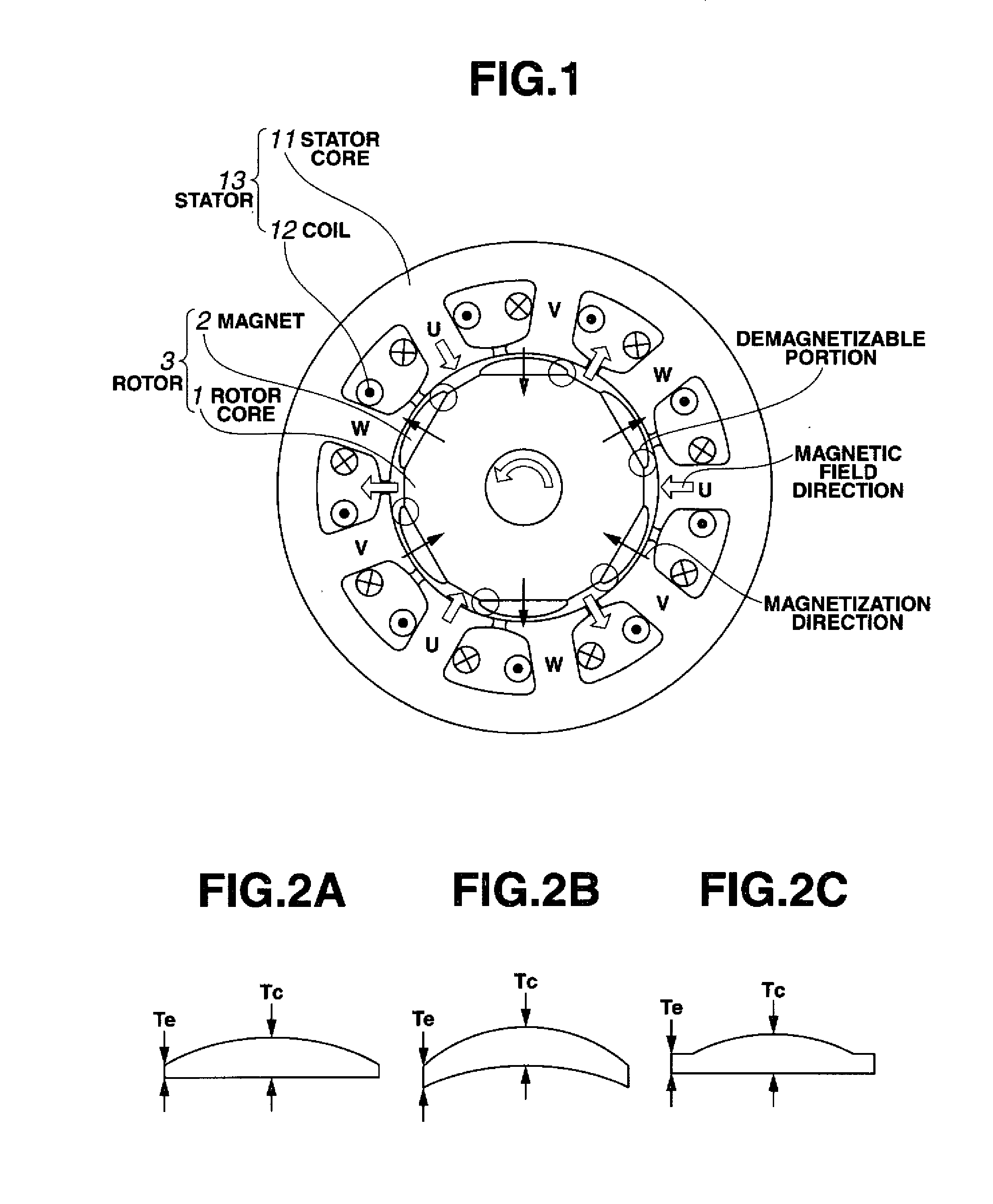
In a rotating machine comprising a rotor including a rotor core and a plurality of permanent magnet segments, and a stator including a stator core and windings, the permanent magnet segment is obtained by disposing a powder comprising an R2 oxide, R3 fluoride or R4 oxyfluoride on a sintered magnet body of R1—Fe—B composition, wherein R1 to R4 are rare earth elements, and heat treating the powder-covered magnet body. The permanent magnet segment of a cross-sectional shape which is tapered from the center toward opposed ends has a higher coercive force at the ends than at the center.
Description
CROSS-REFERENCE TO RELATED APPLICATION [0001] This non-provisional application claims priority under 35 U.S.C. §119(a) on Patent Application No. 2006-233442 filed in Japan on Aug. 30, 2006, the entire contents of which are hereby incorporated by reference. TECHNICAL FIELD [0002] This invention relates to a permanent magnet rotating machine comprising an R—Fe—B permanent magnet obtained by increasing the coercive force of a sintered magnet body while suppressing a decline of remanence (or residual flux density) and more particularly, to a permanent magnet rotating machine best suited as a FA motor or electric power steering motor using a magnet having tapered end portions for the purpose of reducing cogging torque. BACKGROUND ART [0003] By virtue of excellent magnetic properties, Nd—Fe—B permanent magnets find an ever increasing range of application. In the field of rotating machines such as motors and power generators, permanent magnet rotating machines using Nd—Fe—B permanent magne...
Claims
Login to View More Application Information
Patent Timeline
 Patent Type & AuthorityApplications(United States)
IPC IPC(8): H02K1/27H02K15/12
CPCH02K1/02H02K1/278H01F41/0293H02K29/03H01F1/0577H02K15/03H02K1/2781H02K1/27
InventorMIYATA, KOJINAKAMURA, HAJIMEHIROTA, KOICHIMINOWA, TAKEHISA
OwnerSHIN ETSU CHEM IND CO LTD