Illumination apparatus and image projector using the same

a technology of illumination apparatus and image projector, which is applied in the direction of non-linear optics, instruments, printing, etc., can solve the problems of low light utilization efficiency and change in light intensity of illumination light, and achieve the effect of increasing light utilization ratio and reducing the change in illumination light intensity

Inactive Publication Date: 2008-03-06
OLYMPUS CORP
View PDF3 Cites 33 Cited by
  • Summary
  • Abstract
  • Description
  • Claims
  • Application Information

AI Technical Summary

Benefits of technology

[0009]The present invention provides an illumination apparatus and an image projector using the same that can increase the light utilization ratio and decrease a change in intensity of illumination light.

Problems solved by technology

However, with a known illumination apparatus, such as those described above, there is a problem in that the light use efficiency is low since the efficiency of producing linearly polarized light beams before they enter the polarization beam splitter is low.
However, since drive control that takes into consideration the response characteristics of these two units is not carried out, there is a problem in that a change in the light intensity occurs in the illumination light.

Method used


Image

  • Illumination apparatus and image projector using the same
  • Illumination apparatus and image projector using the same
  • Illumination apparatus and image projector using the same

Examples


first embodiment

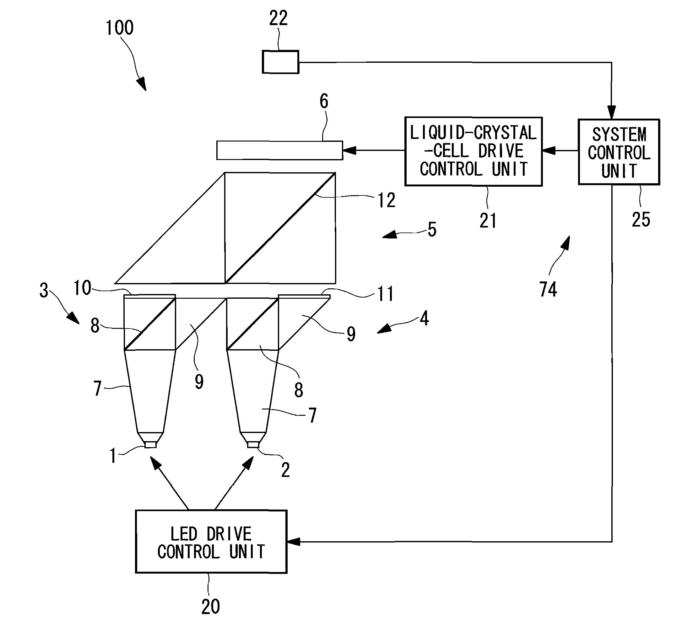
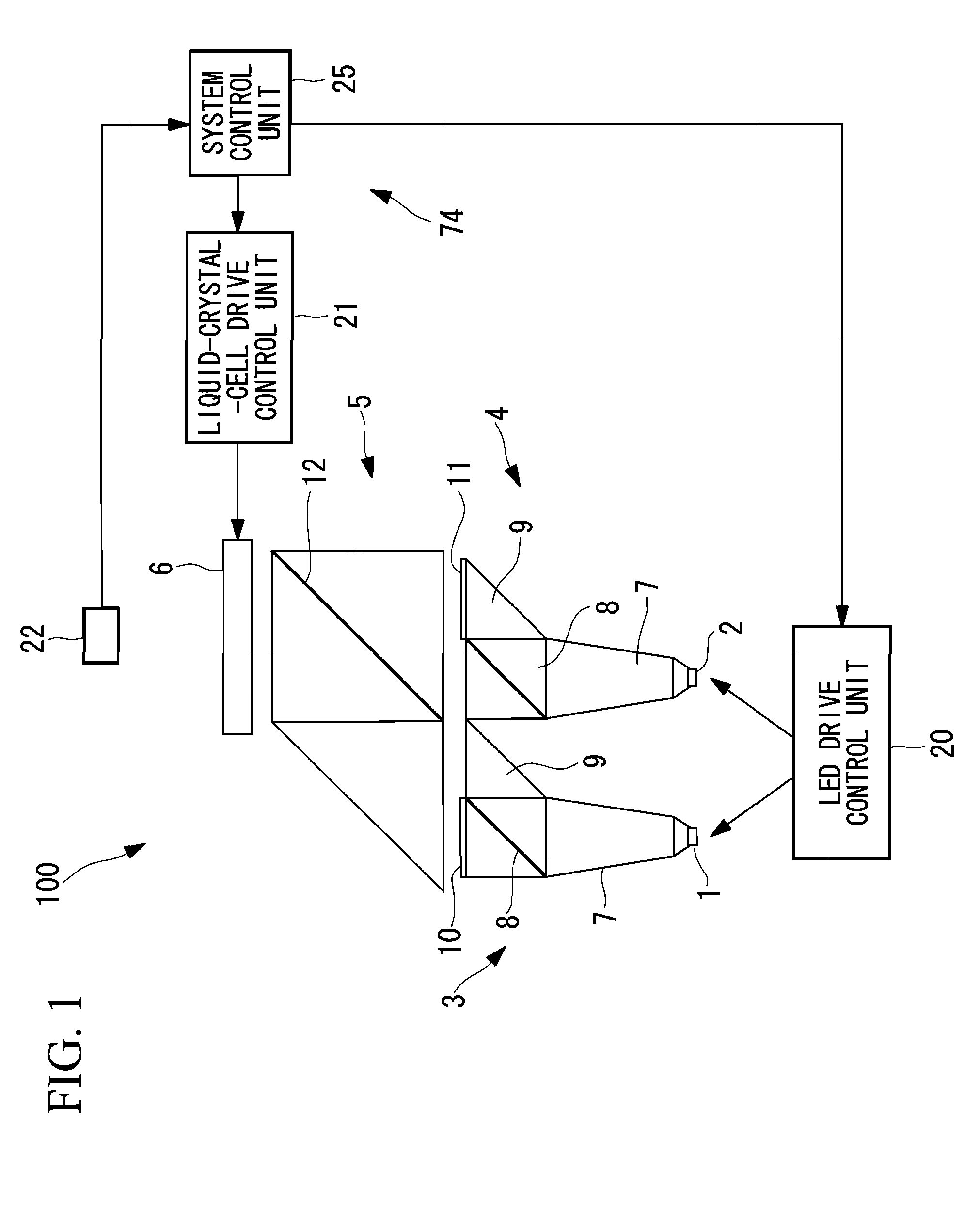
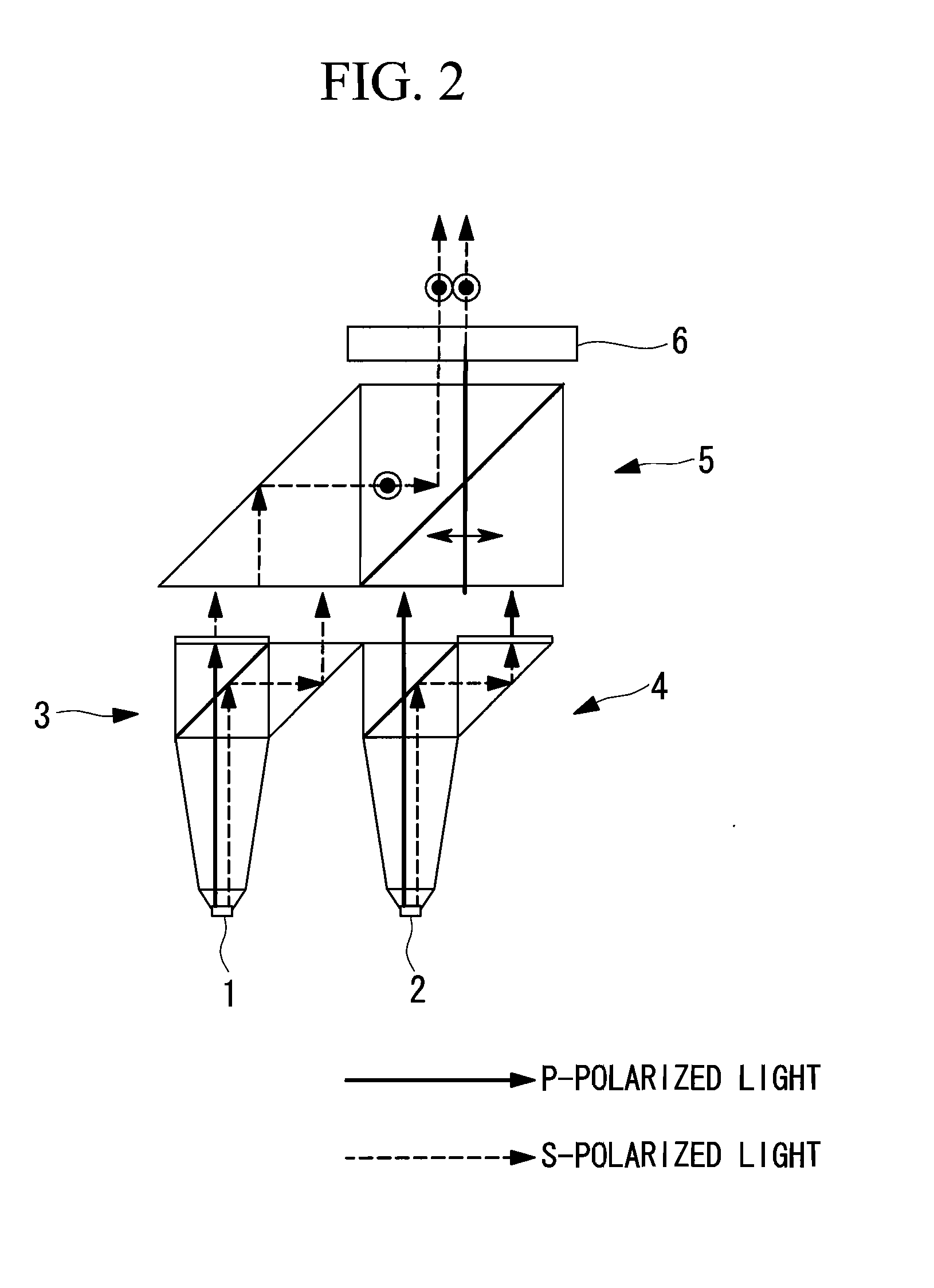
[0085]FIG. 1 illustrates, in outline, the structure of an illumination apparatus 100 according to a first embodiment of the present invention. FIG. 2 illustrates the polarization states of the illumination apparatus 100 illustrated in FIG. 1.

[0086]As shown in FIG. 1, the illumination apparatus 100 according to this embodiment includes a first light-emitting diode (LED: first light source unit) 1, a second LED (second light source unit) 2, a polarization converter unit (first polarization converter unit) 3 that aligns the polarization directions of the illumination light beams emitted from the first LED 1 in a first polarization direction, a polarization converter unit (second polarization converter unit) 4 that matches the polarization directions of the illumination light beams emitted from the second LED 2 to a second polarization orthogonal to the first polarization direction, a light-combining unit 5 that combines the light outputted from the polarization converter unit 3 and the...

first modification

[0122]Next a modification of the above-described illumination apparatus 100 will be described.

[0123]FIG. 10 illustrates a first modification of the illumination apparatus 100. In FIG. 10, instead of the tapered rods 7 shown in FIG. 1, paraboloidal reflectors 31 are provided on backsides of the first LED 1 and the second LED 2 so as to increase the degree of collimation. Unlike the arrangement shown in FIG. 1 in which the first LED 1 and the second LED 2 are arranged in a row, the first LED 1 and the second LED 2 are arranged so that their optical axes are orthogonal to each other. In this way, light-guiding units such as the triangular prism 9 shown in FIG. 1 are not required. Accordingly, the structure of the illumination apparatus 100 can be simplified.

second modification

[0124]FIG. 11 illustrates a second modification of the illumination apparatus 100.

[0125]In the second modification, instead of the tapered rods 7 shown in FIG. 1, compound parabolic concentrators (CPCs) 32 are employed. The degree of collimation of the light from the first LED 1 and the second LED 2 can be increased also by using such CPCs 32. Furthermore, according to this modification, by disposing two polarization beam splitters 8a and 8b at the emission side of each of the CPCs 32, light emitted from the LEDs 1 and 2 can be guided in four optical paths. More specifically, the polarization beam splitters 8a and 8b are disposed at a 45-degree angle to the optical axes of the first LED 1 and the second LED 2 and are disposed such that the surfaces of the polarization splitting films intersect at a right angle. Light reflected at the polarization beam splitters 8a and 8b is incident on the triangular prism and is guided to the light-combining unit 5 via an optical path parallel to t...


PUM

PropertyMeasurementUnit
wavelengthaaaaaaaaaa
luminanceaaaaaaaaaa
light intensityaaaaaaaaaa

Abstract

An illumination apparatus is provided, the illumination apparatus including at least two light-emitting diodes (LEDs) capable of being driven in a flashing manner to output illumination light beams; a polarization converter unit configured to match the polarization directions of the illumination light beams emitted from the at least two light source units; a liquid crystal cell configured to receive the illumination light beams outputted from the polarization converter unit; and a control unit configured to control, in synchronization, the liquid crystal cell and the light source units so as to intermittently drive the light source units and substantially continuously output illumination light beams from the liquid crystal cell.

Description

BACKGROUND OF THE INVENTION[0001]1. Field of the Invention[0002]The present invention provides an illumination apparatus that is capable of supplying high-luminance illumination light and an image projector that includes the illumination apparatus.[0003]This application is based on Japanese Patent Application Nos. 2006-234203 and 2006-343979, the contents of which are incorporated herein by reference.[0004]2. Description of Related Art[0005]In the related art, for example, illumination apparatuses that include a plurality of light-emitting diodes (LEDs), a polarization beam splitter, and a liquid crystal panel and that are capable of outputting light having the same polarization direction have been proposed (Japanese Unexamined Patent Applications, Publication Nos. 2005-257872, 2005-283818, and 2005-183470). By intermittently driving the LEDs of such an illumination apparatus, illumination light having a high overall luminance can be output by applying an electrical current higher t...

Claims


Application Information

Patent Timeline
Patent Type & Authority Applications(United States)
IPC IPC(8): G02F1/1335
CPCG02B27/1033G03B21/2073G02B27/1053G02B27/145G02B27/149G02B27/283G03B27/54H04N9/312H04N9/3155H05B33/0818H05B33/0821H05B33/086G03B21/2033G03B21/2053G03B21/006G03B21/2013G02B27/1046H05B45/20
Inventor HANANO, KAZUNARI
Owner OLYMPUS CORP
Why Eureka
Try Eureka