Projector and Method of Controlling Ultrasonic Speaker in Projector

Inactive Publication Date: 2008-03-06
SEIKO EPSON CORP
View PDF8 Cites 15 Cited by
  • Summary
  • Abstract
  • Description
  • Claims
  • Application Information

AI Technical Summary

Benefits of technology

[0011] In view of the above circumstances, an object of the present invention is to provide a projector and a method of controlling an ultrasonic speaker in the projector, to solve the problem of self-demodulation having directivity of an ultrasonic sound signal emitted to a screen together with images, caused when the signal reflected by the screen still includes a strong ultrasonic signal.
[0016] According to the above structure, the distance between the ultrasonic transducer and the screen is measured by the distance measuring device which may be an ultrasonic sensor. Based on the measured distance data, the carrier frequency of the ultrasonic speaker can be selected and determined by the ultrasonic frequency control device. Generally, it is preferable to secure a desired (i.e., predetermined) sound pressure (e.g., approximately 120 dB) at or in a vicinity of the screen. Therefore, the frequency of the ultrasonic wave signal is controlled so as to secure a predetermined sound pressure (e.g., approximately 120 dB) at or in a vicinity of the screen in accordance with relationships between the frequency and the loss of the ultrasonic wave signal (i.e., attenuation characteristics according to the frequency and the propagation distance in the air). Accordingly, it is possible to secure the desired sound pressure at or in a vicinity of the screen. As a result, even when using an ultrasonic speaker having strong directivity, no self-demodulation of the ultrasonic wave signal reflected by the screen is produced, and human-audible sound, produced by self-demodulation before reflection, is reflected by the screen and spreads over a wide area in a room, which is effective in a home theater or in an environment for the education / culture market.
[0020] In this case, the propagation loss characteristic of the ultrasonic wave signal emitted from the ultrasonic transducer (i.e., attenuation characteristics according to the frequency and the propagation distance in the air) is stored in advance in the storage device of the projector. In accordance with the distance between the ultrasonic transducer and the screen, measured by the distance measuring device, the frequency of the ultrasonic wave signal is determined so as to obtain a desired sound pressure (e.g., approximately 120 dB) at or in a vicinity of the screen. Accordingly, it is possible to secure the desired sound pressure at or in a vicinity of the screen. Therefore, as explained above, even when using an ultrasonic speaker having strong directivity, no self-demodulation of the ultrasonic wave signal reflected by the screen is produced, and human-audible sound, produced by self-demodulation before reflection, is reflected by the screen and spreads over a wide area in a room, which is effective in a home theater or in an environment for the education / culture market.
[0022] In an example, the distance measuring device is an independent device separate from the ultrasonic speaker and employs an ultrasonic sensor for measuring the distance. In this case, the distance measuring device can be efficiently realized by effectively using parts or circuits included in the ultrasonic transducer (for sound signals) mounted in the projector.
[0025] In another example, the distance measuring device includes an ultrasonic transducer which transmits an ultrasonic wave to the screen and also receives a reflected wave from the screen. This ultrasonic transducer is used alternatively for transmitting and receiving the ultrasonic wave by using a switch or the like. Accordingly, the distance between the ultrasonic transducer and the screen can be measured by a single ultrasonic transducer, and the distance measuring device can be economically realized.
[0026] In another example, the ultrasonic transducer (for sound signals) also functions as an ultrasonic sensor for measuring the distance in the distance measuring device. Therefore, no additional ultrasonic sensor is necessary, thereby realizing an economical system.

Problems solved by technology

However, when the above-explained electrostatic ultrasonic transducer is mounted into a projector so as to emit an ultrasonic wave signal onto a screen, the signal reflected by the screen may still include a strong ultrasonic wave due to strong directivity of the ultrasonic signal, and thus self-demodulation having directivity may occur after the reflection.

Method used


Image

  • Projector and Method of Controlling Ultrasonic Speaker in Projector
  • Projector and Method of Controlling Ultrasonic Speaker in Projector
  • Projector and Method of Controlling Ultrasonic Speaker in Projector

Examples


Embodiment Construction

[0042] Hereinbelow, an embodiment of the best mode for carrying out the present invention will be explained with reference to the drawings.

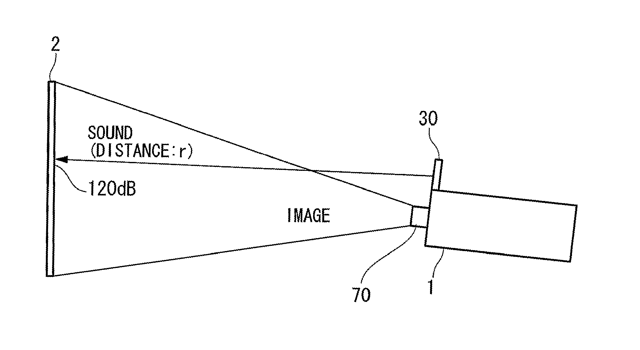
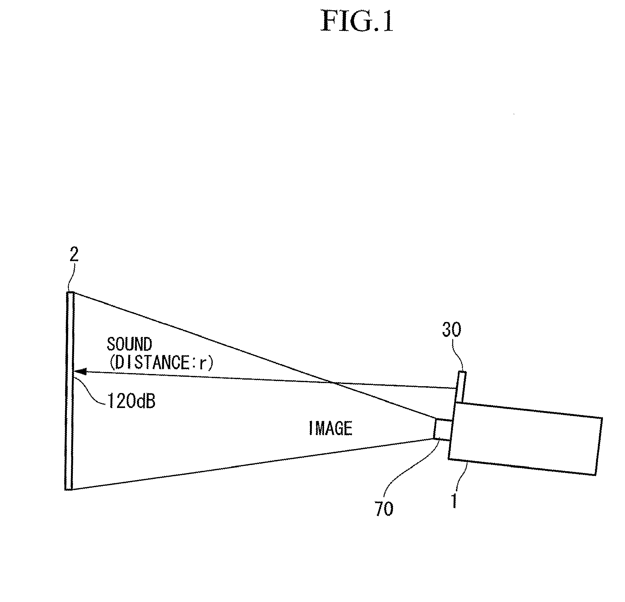
[0043]FIG. 1 is a diagram showing the positional relationship between the projector and the screen in the embodiment. From the projector 1, ultrasonic sound signals are emitted via an ultrasonic transducer 30 together with images which are projected via a projection lens 70. In the ultrasonic emission, what is important is the sound pressure of the ultrasonic waves (signal) on and immediately in front of the screen. When the sound pressure exceeds 120 dB even after reflection, self-demodulation of the reflected sound signal has high directivity and thus the audio (i.e., human-audible) sound reflected by the screen does not spread very much due to remaining directivity.

[0044] Therefore, it is important that the sound pressure of the ultrasonic wave on and immediately in front of the screen 2 is approximately 120 dB. In this case, the audio sound...


PUM


Abstract

A projector having an ultrasonic speaker including an ultrasonic transducer for emitting an ultrasonic wave signal to a screen; a distance measuring device for measuring a distance between the ultrasonic transducer and the screen; and an ultrasonic frequency control device for controlling a frequency of the ultrasonic wave signal based on a measured result of the distance measuring device and a sound pressure of the ultrasonic wave signal emitted by the ultrasonic transducer, so that the ultrasonic wave signal has a predetermined sound pressure at or in a vicinity of the screen. The projector may include a storage device for storing a propagation loss characteristic in air of the ultrasonic wave signal emitted from the ultrasonic transducer. The ultrasonic frequency control device controls the frequency of the ultrasonic wave signal by referring to the propagation loss characteristic of the ultrasonic wave signal stored in the storage device.

Description

TECHNICAL FIELD [0001] The present invention relates to a projector using an ultrasonic speaker for generating a certain high sound pressure over a wide frequency range and to a method of controlling the ultrasonic speaker in the projector, and in particular, relates to the projector and the control method for solving a problem of self-demodulation having directivity of an ultrasonic sound signal emitted to a screen together with images, caused when the signal reflected by the screen still includes a strong ultrasonic signal. [0002] Priority is claimed on Japanese Patent Application No. 2004-202740, filed Jul. 9, 2004, the content of which is incorporated herein by reference. BACKGROUND ART [0003] It is conventionally known that ultrasonic speakers using a non-linear effect of the medium (i.e., air) on an ultrasonic wave (signal) can reproduce a signal in an audio (i.e., human-audible) frequency band, which has far higher directivity in comparison with normal speakers. Representativ...

Claims


Application Information

Patent Timeline
IPC IPC(8): G03B31/00H04R5/02G10K15/02H04R1/00H04R1/34
CPCB06B1/0603B06B2201/51H04R2217/03G10K11/28G10K11/26G10K15/02H04R1/00H04R1/34H04N5/74
Inventor MATSUZAWA, KINYA
Owner SEIKO EPSON CORP
Why Eureka
Try Eureka