
Active modular optoelectronic components

Inactive Publication Date: 2008-03-06
OPTOGIG
View PDF18 Cites 52 Cited by
  • Summary
  • Abstract
  • Description
  • Claims
  • Application Information

AI Technical Summary

Benefits of technology

[0023]Moreover, the active fiber optic modules of the present invention can be either hot pluggable or soldered to their respective PC boards. I

Problems solved by technology

The dual SC port arrangement limited the minimum size of the ports that could be stacked together.
Until now, no known optical interface has been able to successfully address this need f

Method used


Image

  • Active modular optoelectronic components
  • Active modular optoelectronic components
  • Active modular optoelectronic components

Examples


Example

DETAILED DESCRIPTION OF THE DRAWINGS

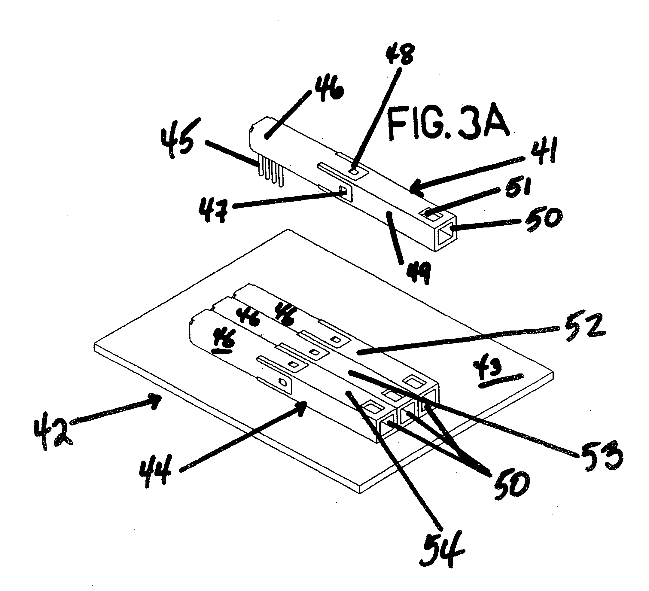
[0056]Reference will now be made to other aspects of the drawings, to describe the invention. It is to be understood that the drawings are diagrammatic and schematic representations of certain embodiments and are not limiting of the present invention, nor are they necessarily drawn to scale.

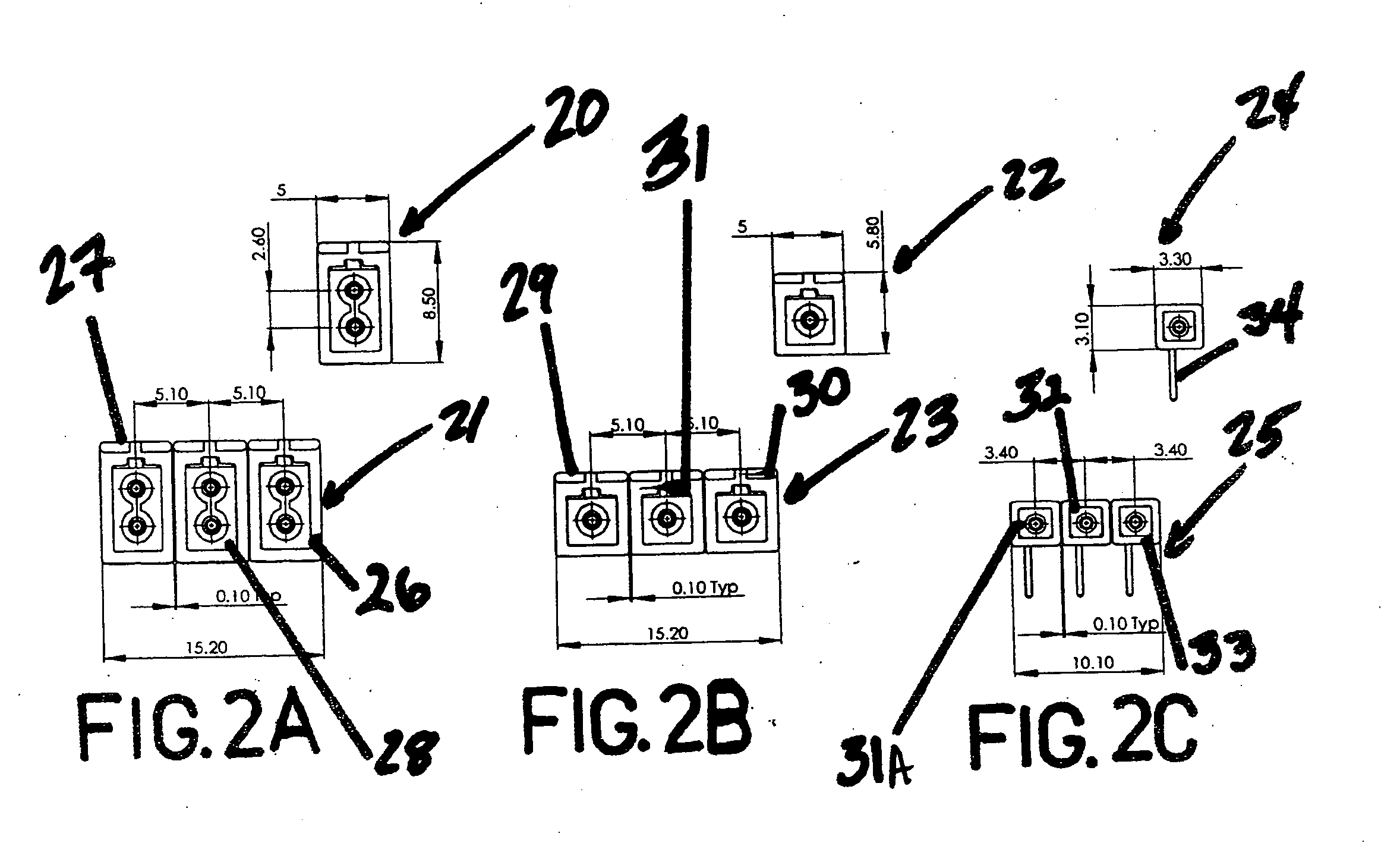
[0057]Duplex unit 21 comprises modules 26, 27 and 28 of FIG. 2A arranged in a triplet or three-across configuration. Modules 26, 27, 28 can be transceivers, transmitters or detectors depending upon the active components contained in each. For example, if module 26 contains both a transmitter and a detector as its two active components, then it would be a transceiver.

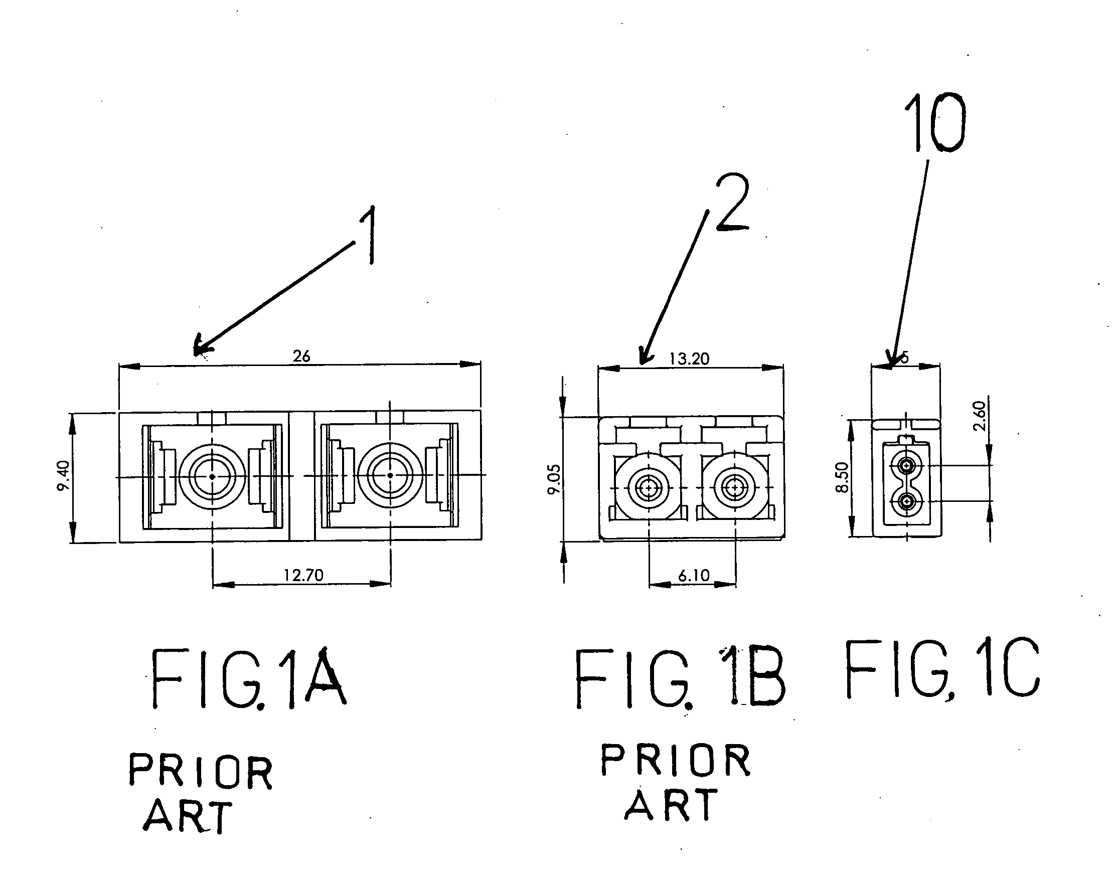
[0058]The footprint of a module is defined as the height versus the width of the module. Also shown in FIG. 2A is single duplex module 20 having a footprint of only 5.0 mm wide by 8.5 mm high. The ferrule center to center vertical distance of duplex module 20 is only 2.6 mm. As shown in FIG. 2A the ...


PUM


Abstract

Super miniature TFF and TFP active modular optoelectronic components are based on an optical interface that is substantially less than half the size of SFF/SFP components and more than five times smaller than an SC based component and provides a density that is three times higher than LC interfaces. The invention provides substantially smaller passive interconnect systems that can be used with substantially smaller photonic devices and combines the new photonic devices with the new smaller miniature interconnect systems such as the Push-Push Interconnect system. The new interface can be used with 0.8 mm or larger interfaces. Photonic devices are mounted directly on the active end of a ferrule thereby enabling use with coatings, avoiding the need for lenses, enabling use in active hermetic or non-hermetic subassemblies, and enabling use of optional posts to set the separation of the photonic device from the fiber.

Description

THE FIELD OF THE INVENTION[0001]The invention relates to the field of communication along a fiber optic channel. More specifically, the invention relates to active fiber optic components or photonic devices such as transceivers, transmitters and receivers that can be used with sub-millimeter diameter interconnect systems.BACKGROUND OF THE INVENTION[0002]Fiber optic transceiver modules, also known as optoelectronic transceivers, transmit optical signals and receive optical signals. Such transceivers provide for the bi-directional communication of signals between an electrical interface and an optical interface. A fiber optic transceiver includes a circuit board that contains at least a receiver circuit, a transmit circuit, a power connection and a ground connection.[0003]Transceivers and other active fiber optic modules are miniaturized in order to increase the port density associated with the network connection with respect to switch boxes, cabling patch panels, wiring closets, comp...

Claims


Application Information

Patent Timeline
IPC IPC(8): G02B6/36
CPCG02B6/4201G02B6/4292G02B6/4202G02B6/4251G02B6/4256
Inventor MARGOLIN, MARKBUNIN, GREGORY
Owner OPTOGIG
Features
  • Generate Ideas
  • Intellectual Property
  • Life Sciences
  • Materials
  • Tech Scout
  • Unparalleled Data Quality
  • Higher Quality Content
  • 60% Fewer Hallucinations
Learn More