Axial turbine

a technology of axial turbine and axial shaft, which is applied in the direction of machines/engines, stators, liquid fuel engines, etc., can solve the problems of reducing the output power of the stage, the inability to provide a plurality of balance holes in a circumferential direction, etc., to prevent the decrease in the output power of the stage, the effect of preventing the interference of the blowout flow and improving the efficiency of the turbine stag

Inactive Publication Date: 2008-03-06
HITACHI LTD
View PDF5 Cites 39 Cited by
  • Summary
  • Abstract
  • Description
  • Claims
  • Application Information

AI Technical Summary

Benefits of technology

[0013]According to the present invention, since the flow blowing out from the space between the stator blades and the moving blades is bent in the rotational direction of the rotor, it is possible to suppress interference of the blowout flow with a main flow of steam that has run in from an upstream direction between stator blades, and consequently to prevent a decrease in stage output power to occur, thereby improving turbine stage efficiency.

Problems solved by technology

The method of providing a plurality of balance holes in a circumferential direction cannot be used for an axial turbine not having such a space as a drum-type rotor in which to provide the balance holes.
However, this blowout flow will, as detailed later herein, interfere with the flow that has run in from an upstream direction as the main flow of steam between stators, and the interference will disturb the main flow of steam, thus reducing the output power of the stage.

Method used


Image

  • Axial turbine
  • Axial turbine
  • Axial turbine

Examples


Embodiment Construction

[0022]Hereunder, an axial turbine having a turbine stage according to a first embodiment of the present invention will be described by using the accompanying drawings.

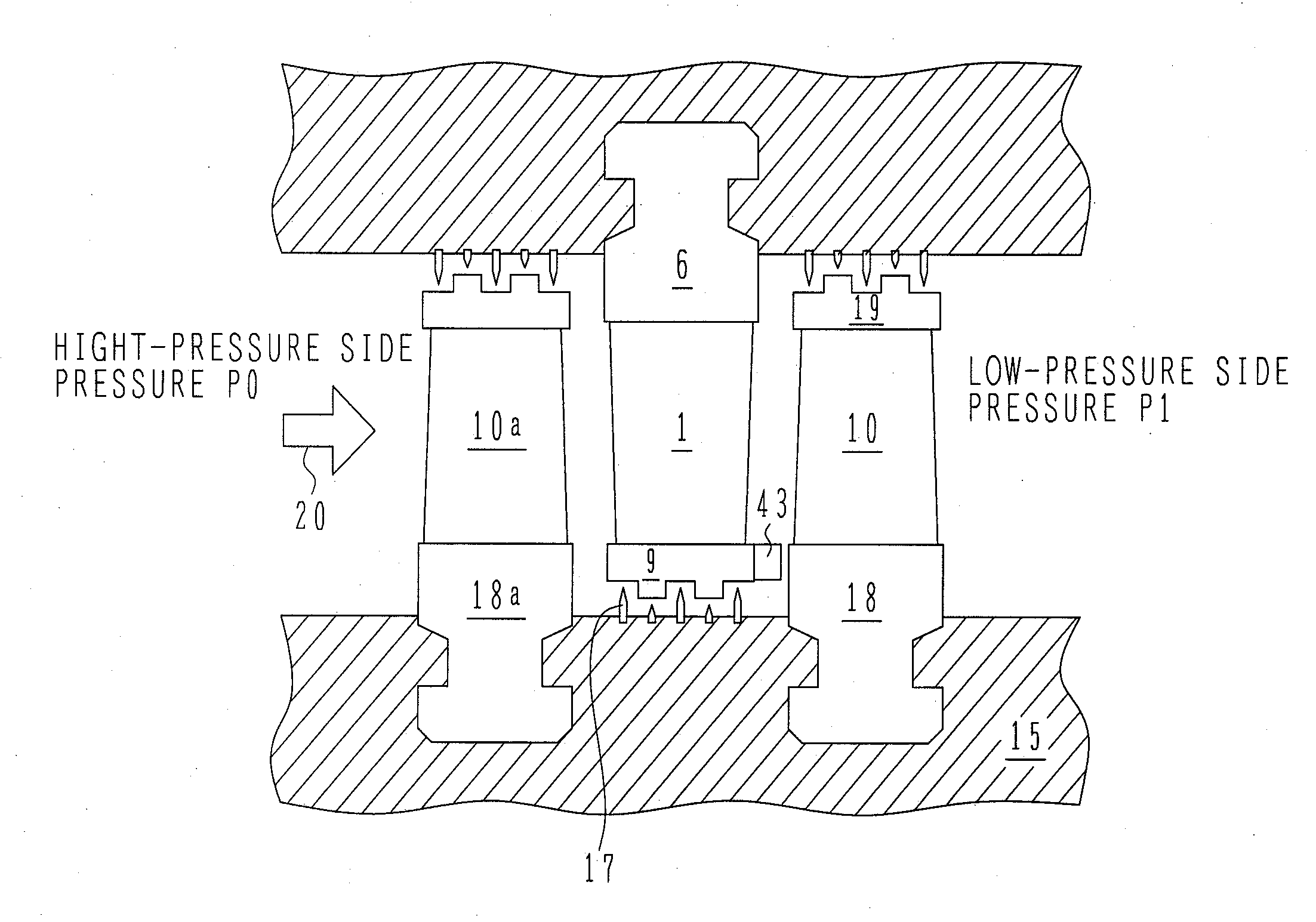
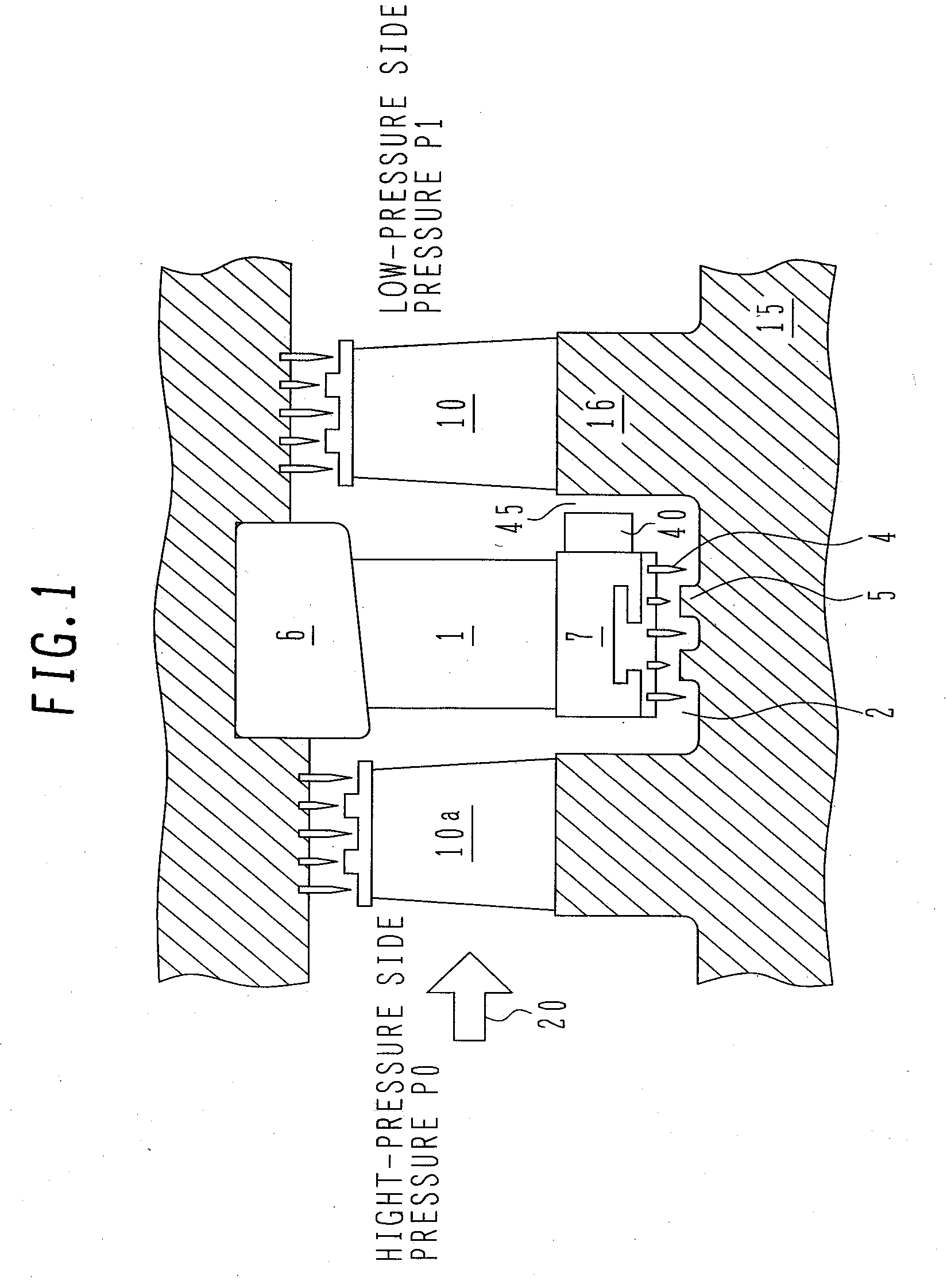
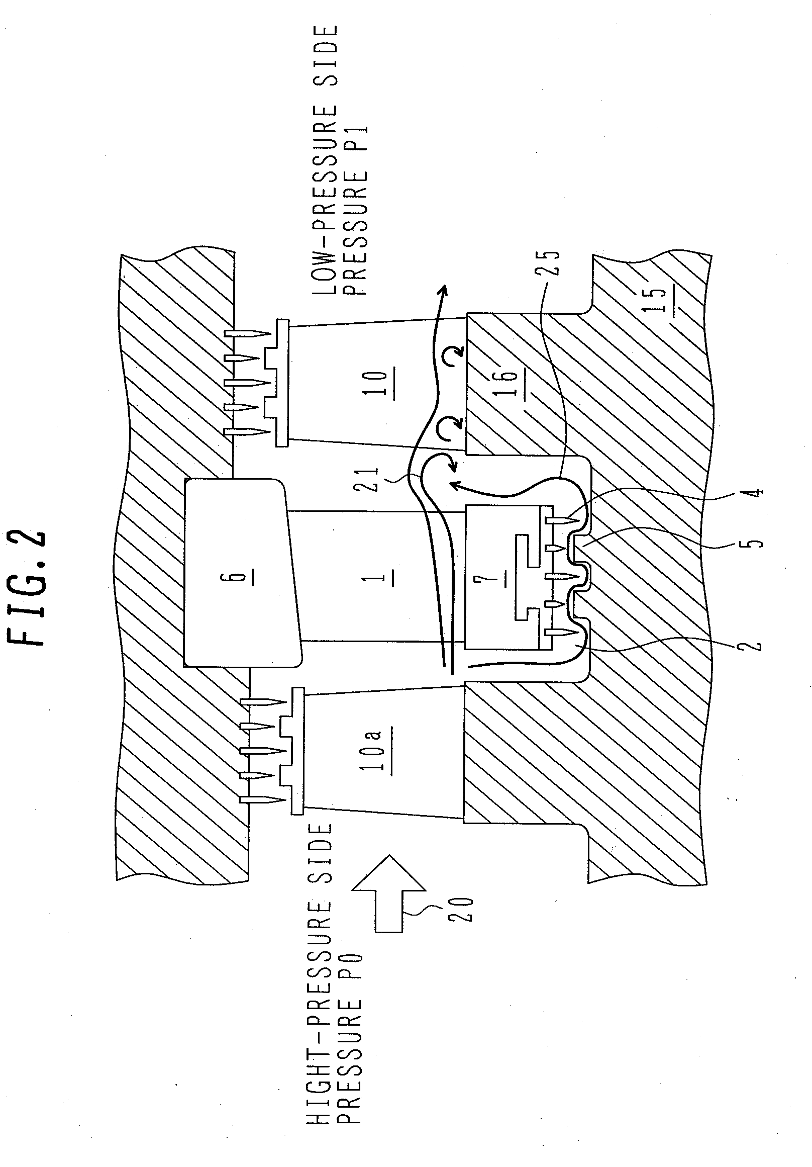
[0023]A sectional view of the turbine stage of the present invention is shown in FIG. 1. As shown therein, the turbine stage is provided between a high-pressure side P0 and a low-pressure side P1, and includes stator blades 1 fixed to an outer circumferential diaphragm 6 and an inner circumferential diaphragm 7, and moving blades 10 provided on a rotor 15 that rotates. In case of a turbine having a plurality of turbine stages, moving blades 10a of another stage exist at an upstream side of the stator blades 1.

[0024]A main flow of steam 20 is induced by a differential pressure P0-P1, and the flow 20 is speeded up by the stator blades 1 and deflected in a circumferential direction thereof. The flow to which the circumferential velocity component has been assigned by the stator blades 1 gives kinetic energy to the moving ...


PUM


Abstract

An axial turbine has a turbine stage including stator blades fixedly provided on a stationary section and moving blades fixedly provided on a rotating section and has a structure in which a flow blowing out from a space formed between the stator blades and the moving blades exists. In order to prevent a decrease in stage output power due to such blowout flow thereby to improve the turbine stage efficiency, the axial turbine comprises a member coupling an inner circumferential side of the stator blades, and a structure provided on a surface of the member opposed to the moving blades for bending a flow blowing out from the side of the rotating section into a space between the stator blades and the moving blades in a rotational direction of the rotating section.

Description

BACKGROUND OF THE INVENTION[0001]1. Field of the Invention[0002]The present invention relates to axial turbines and more particularly to a drum-type rotor turbine.[0003]2. Description of the Related Art[0004]The axial turbine such as a steam turbine or gas turbine comprise a turbine stage including stator blades formed to transform the pressure of a fluid into kinetic energy and moving blades for transforming the pressure or kinetic energy of the fluid into the rotational energy of a rotating section. The stator blades are fixedly provided between an outer circumferential diaphragm and inner circumferential diaphragm forming a stationary section. The moving blades are provided on a rotor that forms the rotating section. A clearance is provided between the inner circumferential diaphragm and the rotor, and the clearance has a seal. This seal reduces a leakage flow that passes through the clearance. This leakage flow passing through the clearance, however, cannot be completely zeroed ...

Claims


Application Information

Patent Timeline
Patent Type & Authority Applications(United States)
IPC IPC(8): F04D29/40
CPCF01D5/143F01D5/145F05D2240/56F01D11/02F01D11/001F05D2240/126F05D2240/129F04D29/32F04D29/38
Inventor SENOO, SHIGEKI
Owner HITACHI LTD
Why Eureka
Try Eureka