
Motion fuel cell

a technology of motor fuel cell and fuel cell, which is applied in the direction of fuel cell, fuel cell auxilary, electrical apparatus, etc., can solve the problems of inability to reform fuel, low energy density of pure hydrogen, and inability to achieve on-board reforming, etc., and achieve excellent water management and optimal reactant gas diffusion performance.

Inactive Publication Date: 2008-03-06
MCELROY RICHARD LEE
View PDF0 Cites 9 Cited by
  • Summary
  • Abstract
  • Description
  • Claims
  • Application Information

AI Technical Summary

Benefits of technology

The invention provides a new fuel cell system that optimizes reactant gas diffusion, water management, and cooling performance. It reduces harmful hotspots and moisture ridden areas, and increases overall electrochemical activity. The system offers improved performance without the need for costly high-pressure delivery compressors and can be used with different fuel cell technologies. It also allows for unlimited provision of reactant to electrodes and reduces power drag. The invention achieves these benefits by rotating cylindrically shaped electrodes at low or ambient pressures, rather than through limited static channels, resulting in greater contact opportunity per second between electrodes and reactant. It also provides ideal pressure differences between the anode and cathode for better electrochemical performance. Overall, the invention offers a new solution for improving fuel cell performance.

Problems solved by technology

These varied types of fuel cells are continually being further developed; however, with certain advantages and limitations to any particular application.
As referenced above, the low energy density of pure hydrogen, as a fuel, presents a problem for a PEM fuel cell fed by pure hydrogen, when concerning on-board fuel supply and range in transportation applications.
The reforming of fuel, on-board, i.e. extracting pure hydrogen from hydrogen rich fuels for use in the fuel cell, is not a possible option at present because reformers require high heat to function; and conventional low heat PEMs do not provide the heat by-product needed.
One of the major contributing factors to cost at this time remains precious metal loading at the electrodes (particularly at the cathode).
The DOE states progress has been made in developing fuel cell membranes that are capable of operating at 120 degrees C., or above, toward lessening this problem; however, greater humidification remains an issue at the anodic side of the polymer membrane.
In addition, it has been a practice, particularly in PEM fuel cell technology, to entrain water into the fuel supply to help rehydrate the membrane; however, it is found that over hydrating this way can cause a moisture film to build up at the anode-electrode surface; hindering fuel contact with the said electrode, limiting the amount of water that can be entrained with the fuel to benefit the said membrane.
This problem is aggravated, in prior art, by the high cost and by the limited performance and capability of minute and complex flow-channels, by necessity, engraved into carbon backing plates (used in flat plate fuel cells) to distribute reactant to electrodes (and to carry by-product water away) within a closed pressure delivery system.
However, the parasitical drag, cost, bulk, capacity and reliability of the compressors being developed, to provide such, remain issues.
For example, the durability of such compressors depend on effective lubrication for friction and wear reduction in critical components, which according to the DOE, the lubricants needed, with respect to present technology, can contaminate and poison the electrodes in the fuel cell stack.
Although critical components are being developed, the durability, cost, bulk, capacity and the parasitical power drag on the overall system output, remain issues.
It is known, with the desired higher density output of any fuel cell system comes the inherent problem of staying ahead of an over humidified and moisture ridden cathode.

Method used


Image

  • Motion fuel cell
  • Motion fuel cell
  • Motion fuel cell

Examples


Embodiment Construction

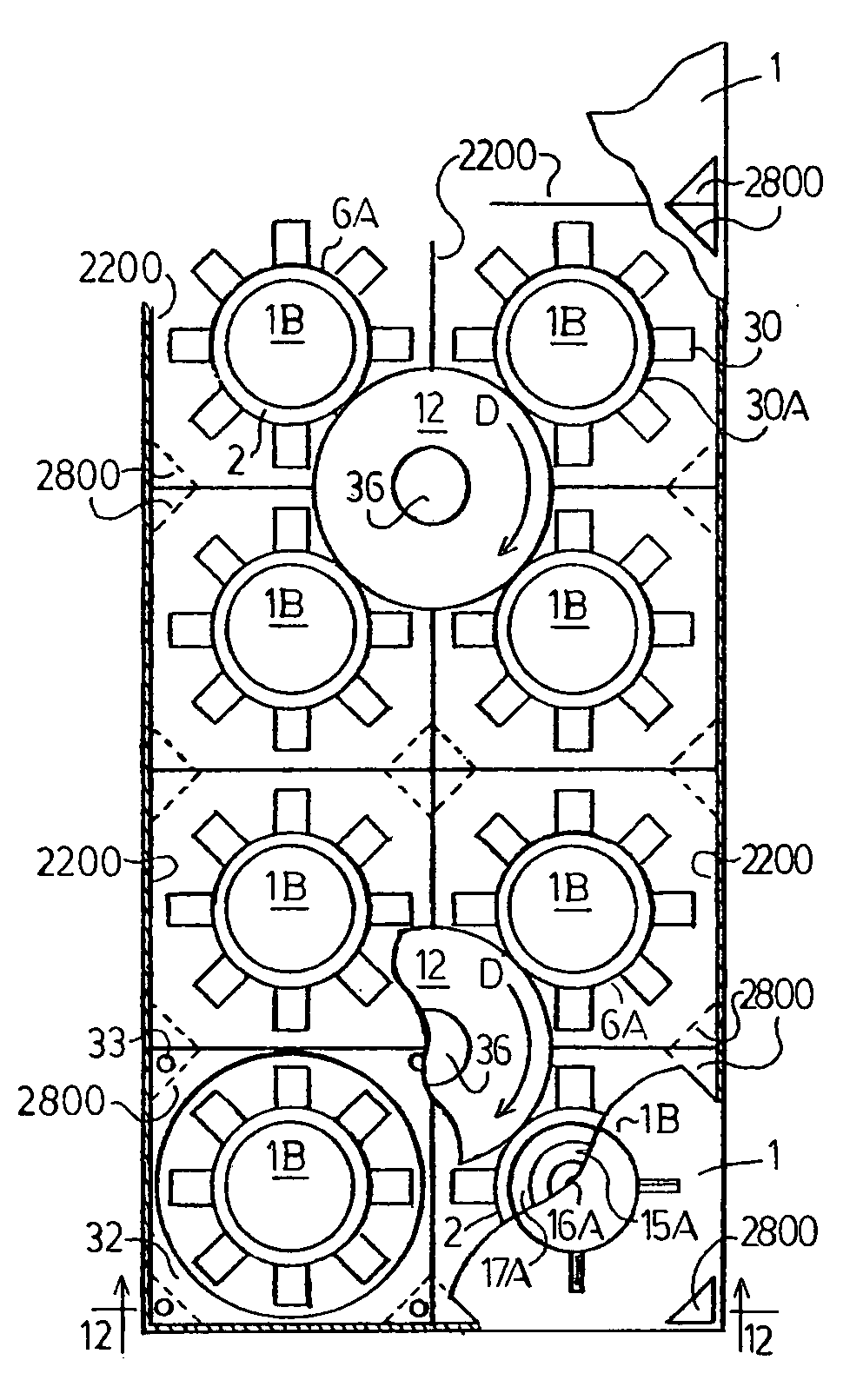
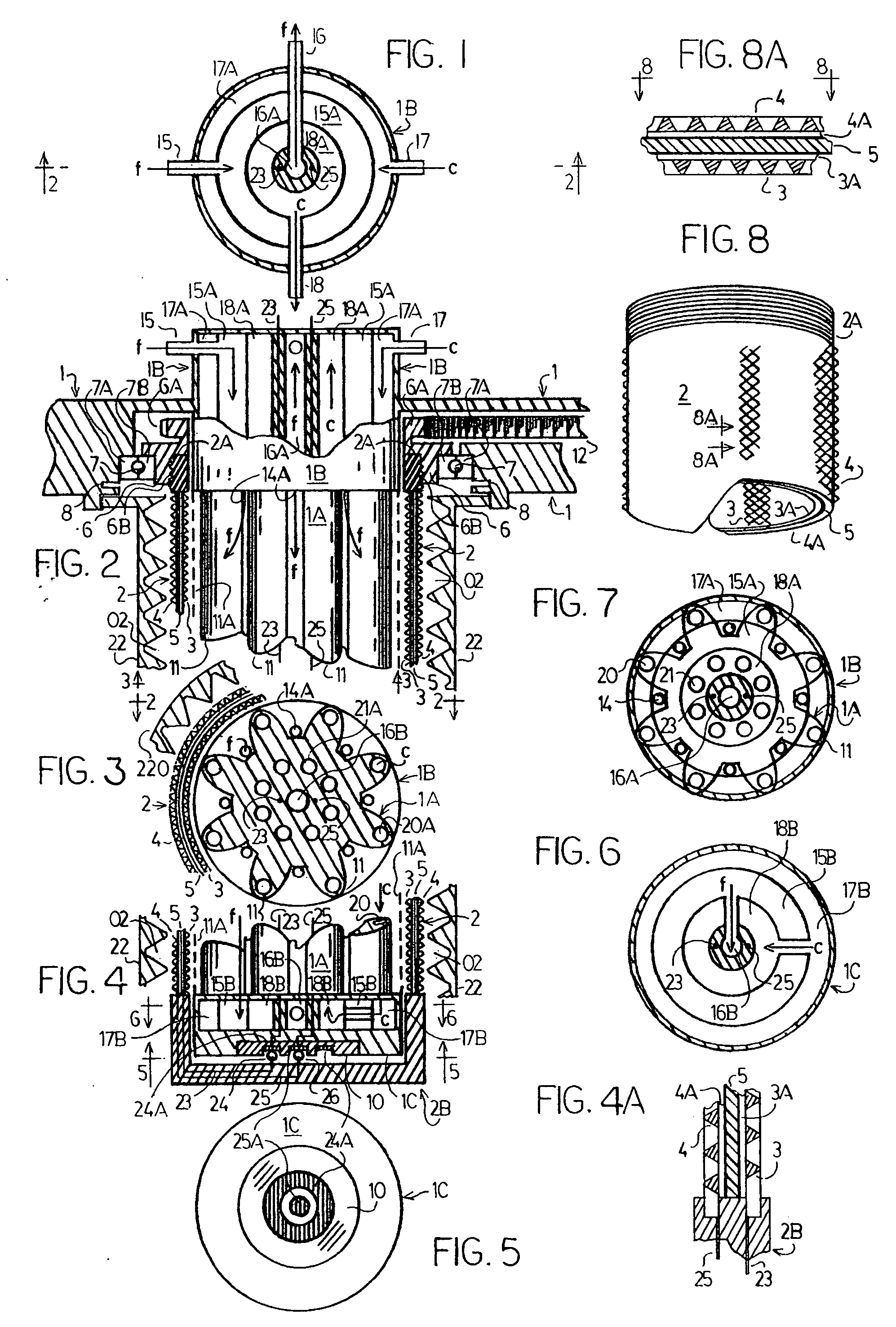
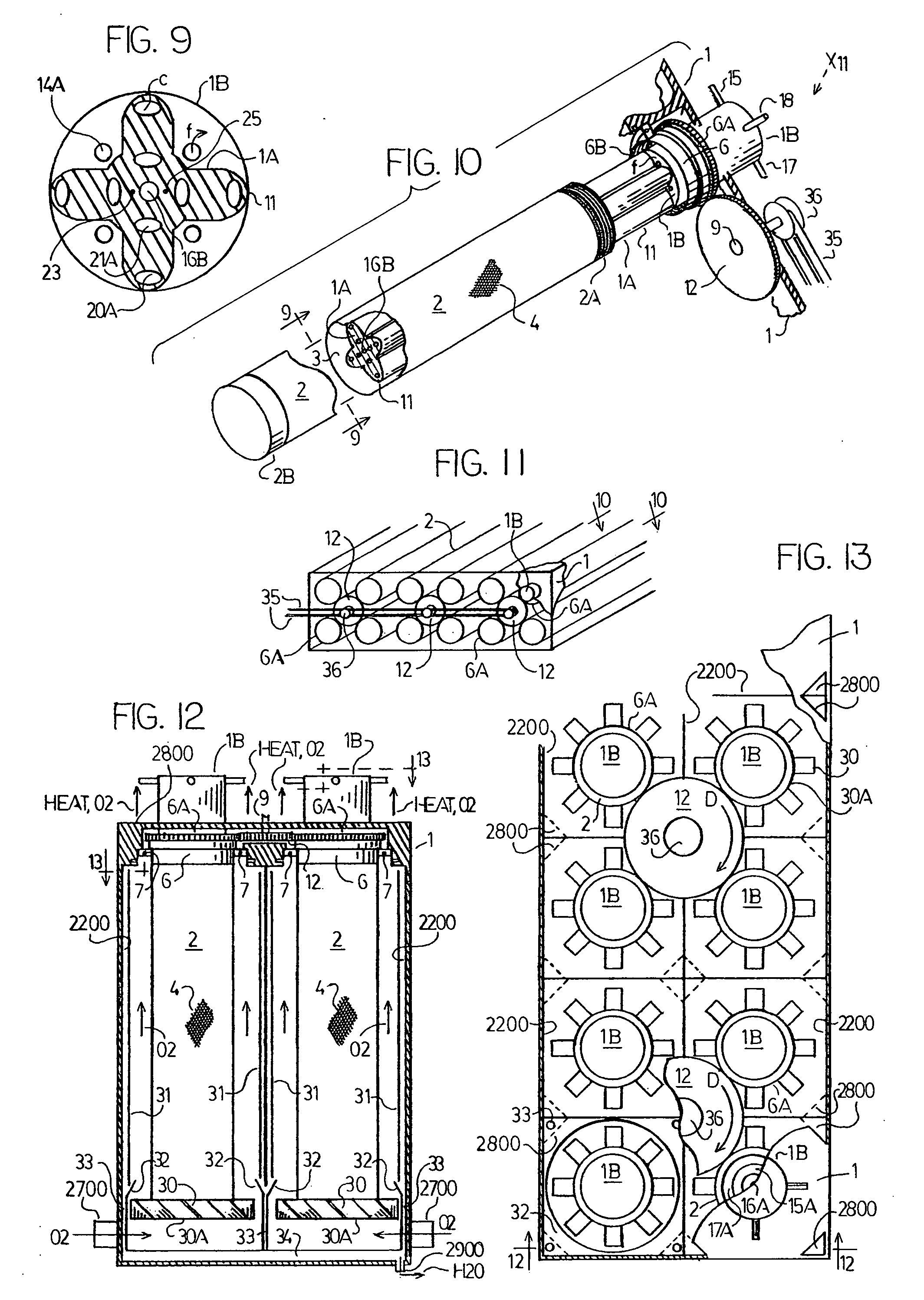
[0075] In referring to first 3 drawing pages (numbered: 1 of 6, 2 of 6 and 3 of 6), and in particular to FIGS. 1 and 2; the stationary main structure 1 is the structural support and outer wall of the system. The stationary structure 1, supports (in a fixed position) the fuel and cooling delivery bar (or FC bar 1A), and the end manifold units 1B and 1C which are the connected end portions and part of the said FC bar 1A. The extended stationary structure 1, in addition, supports a greater plurality of (FC bar 1A, 1B and 1C) fuel cell units; including a plurality of powered gear systems 12, which engage the rotary drive mechanism of each fuel cell unit.

[0076]FIG. 1 is taken along lines 1-1 in FIG. 2, and is a top view (relative to FIG. 2) of the main manifold 1B; comprising: the fuel-reactant, or fuel (F), entry valve 15; and fuel exit valve 16; and the coolant-medium, or coolant (C), entry valve 17; and coolant (C) exit valve 18; and the concentric chambers of each, respectively, 15A...


PUM

PropertyMeasurementUnit
pressuresaaaaaaaaaa
currentaaaaaaaaaa
motion-movementaaaaaaaaaa

Abstract

A fuel cell system (with reference to a single cell arrangement) comprising means to provide for the motion-movement of an assembly comprised of an electrolyte sandwiched between an anode-electrode and a cathode-electrode; said motion-movement serving to accelerate electrochemical activity within the fuel cell by providing for accelerated reactant exposure to respective electrodes; including instant centrifugal water removal at the cathode-electrode surface; and boosted cooling to said anode-electrode; while offering accelerated (anti electroosmotic) moisturizing to the specific benefit of the anode side of a polymer-electrolyte.

Description

BACKGROUND OF THE INVENTION [0001] 1. Technical Field [0002] The present invention relates to electrochemical fuel cells in general; of which, conventionally, the components of a single unit cell would include: an electrolyte sandwiched between an anode-electrode and a cathode-electrode and the interconnect material. The invention is particularly directed to accelerated electrochemical activity, improvements in reactant distribution, improved water management and removal at cathode, controlled anodic cooling; and with particular reference to polymer electrolyte membrane (PEM) fuel cells: increased humidification to the anode side of the PEM; and in any fuel cell, enhancing potential advantages and overcoming certain limitations that will benefit transportation and or stationary applications. [0003] 2. Background Art [0004] There are well known various constructions and diverse types of fuel cells; and they are primarily classified by the type of electrolyte employed, which determine...

Claims


Application Information

Patent Timeline
Patent Type & Authority Applications(United States)
IPC IPC(8): H01M8/02H01M2/02H01M8/04H01M2/08
CPCH01M8/0252H01M8/04156Y02E60/50H01M8/2475H01M8/2445H01M8/2483H01M8/241H01M8/2457
Inventor MCELROY, RICHARD LEE
Owner MCELROY RICHARD LEE
Learn More