Wireless headset with bypass mechanism

a bypass mechanism and wireless headset technology, applied in the field of wireless headsets with bypass mechanisms, can solve the problems of affecting the use of users, and affecting the use of headsets

Inactive Publication Date: 2008-03-06
SMITH DALE TRENTON
View PDF25 Cites 68 Cited by
  • Summary
  • Abstract
  • Description
  • Claims
  • Application Information

AI Technical Summary

Benefits of technology

[0008]The principles of the present invention relate to a wireless headset configured to communicate with a wireless transceiver over a wireless signal path. The wireless headset includes at least

Problems solved by technology

The cord from such wired headsets, however, often may get in the way of a user's movement, and is frequently responsible for pulling the headset from its most comfortable position on the user's head.
Often, the plugs on the end of a headset cord become intermittent due to the frequent strain put on them when users accidentally pull on or sit on the cord.
In larger aircraft or in emergency vehicles, a cord can interfere with the responsibilities of crew members, so headsets are removed and communication sacrificed while some duties are performed.
However, existing wireless headsets introduce other problems which often limit their use in noisy environments and environments where communications are critical, such as in an aircraft or emergency vehicle.
For example, one limitation of existing wireless headsets is that they typically rely on batteries and will lose power if the batteries are not recharged or replaced.
The exclusive use of battery power causes many existing wireless headsets to not use Active Noise Reduction (ANR), as ANR consumes more battery power.
In addition, the battery status is often provided with visual indicators such as Light Emitting Diodes which are insufficient to capture the user's attention when pilot or crew workload is high.
A further limitation o

Method used


Image

  • Wireless headset with bypass mechanism
  • Wireless headset with bypass mechanism
  • Wireless headset with bypass mechanism

Examples


Embodiment Construction

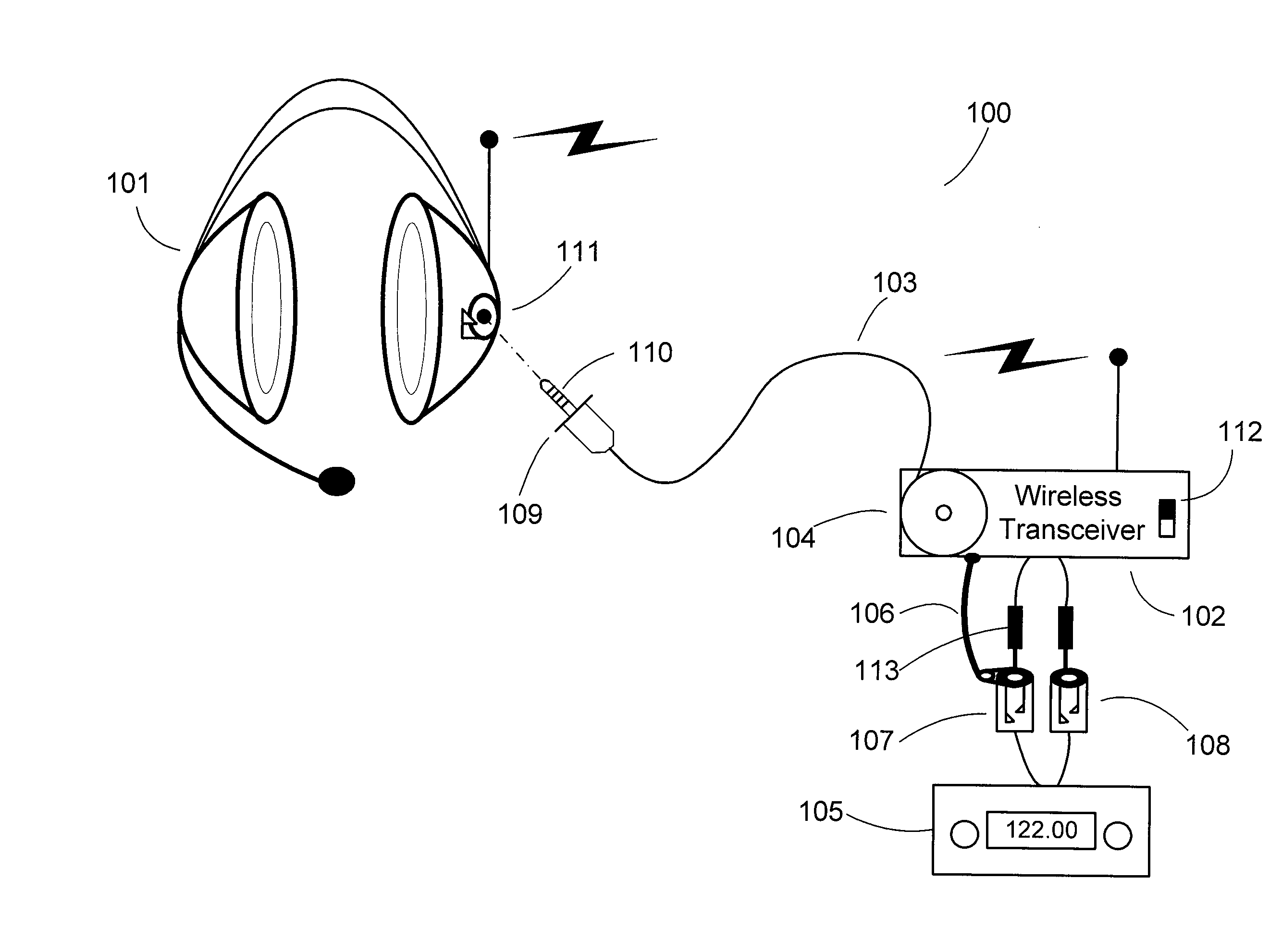
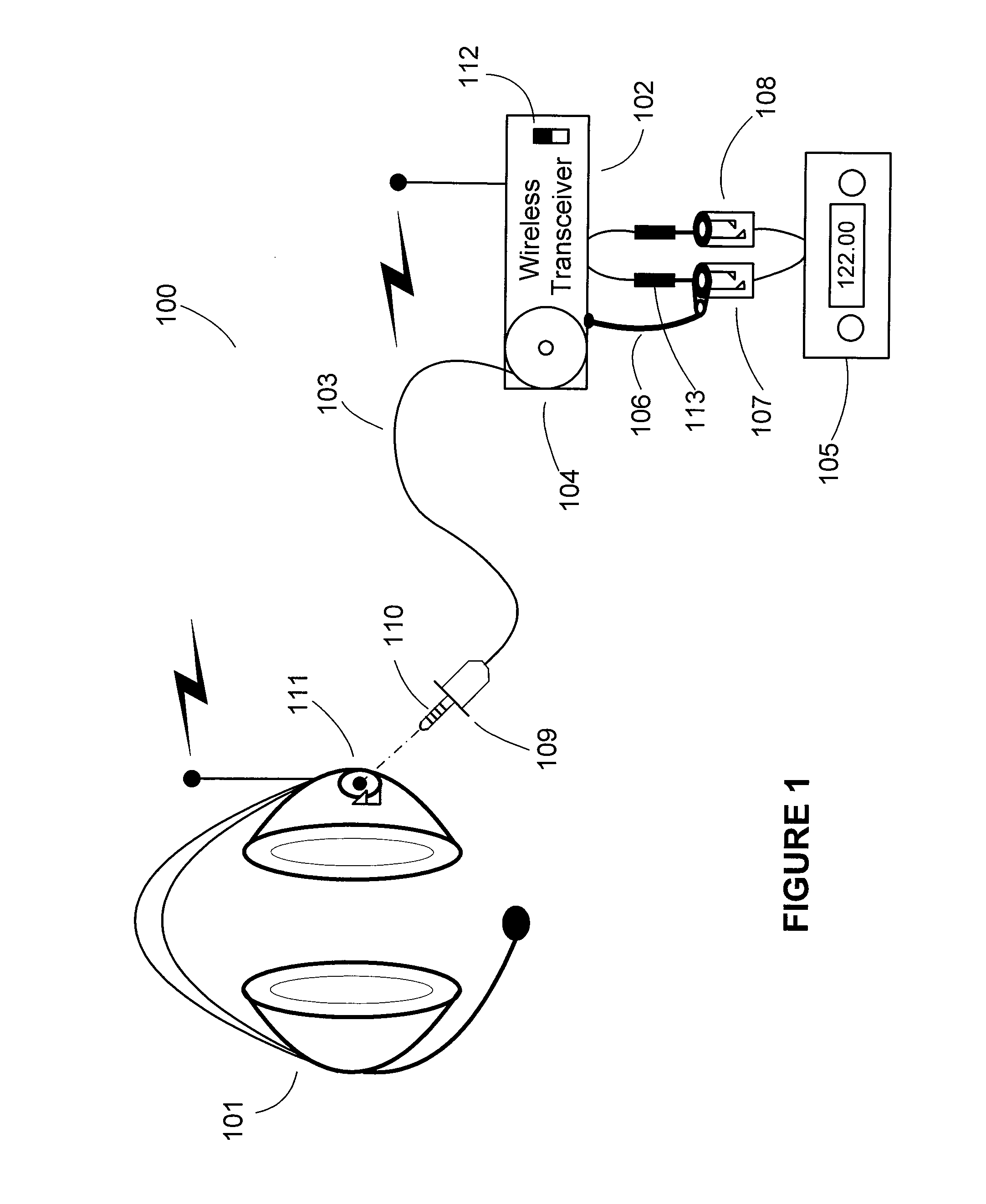
[0027]The principles of the present invention relate to a wireless headset that may be integrated with a variety of diverse systems, consisting of radios, intercoms and audio selectors. These may provide stereo or mono sound. Some headsets, such as in aircraft or emergency vehicles, need to communicate through VHF radios while other headsets on the same intercom do not. Some headsets in a system may be mission critical, while others in the same system are for entertainment purposes. A wireless headset system may consist of a single headset, or multiple headsets communicating with each other.

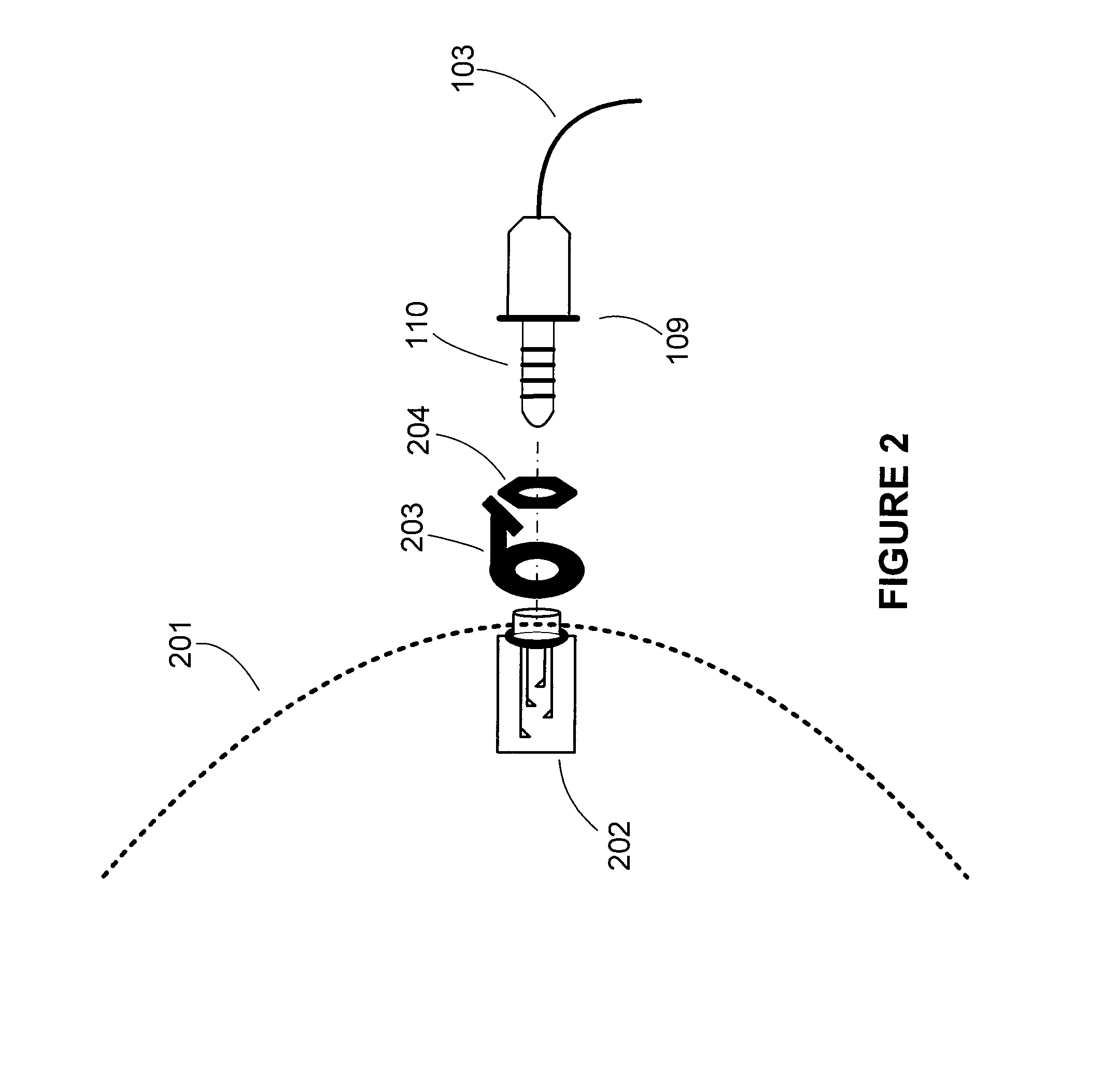
[0028]A wireless headset system typically consists of both the wireless headset and a wireless transceiver which converts wired audio signals to wireless. Generally, the wireless transceiver must adapt the wireless headset to the specific operating requirements of a particular audio system. One embodiment of the wireless headset system consists of a single wireless headset design which can be cou...


PUM


Abstract

The present invention relates to a wireless headset configured to communicate with a wireless transceiver over a wireless signal path. The wireless headset includes speakers and a microphone one or more batteries for providing power to the wireless headset; and a connector configurable to receive a bypass cord for bypassing the wireless audio path with a wired signal path. Further embodiments of the wireless headset include speakers and a microphone, Active Noise Reduction (ANR) circuitry; and a connector configurable to receive a bypass cord for bypassing the wireless audio path with a wired signal path. Additional embodiments of the wireless headset include speakers and a microphone and a connector latch for latching a bypass cord to the wireless headset, wherein the bypass cord is configured to bypass the wireless signal path with a wires signal path.

Description

CROSS-REFERENCE TO RELATED APPLICATIONS[0001]Not applicable.BACKGROUND OF THE INVENTION[0002]Aviation headgear is used by professional and private pilots throughout the world. The purpose of this headgear is to enable the pilot to communicate with the ground and with the co-pilot unimpeded by background noise. Most general aviation aircraft were originally built with a hand held microphone and a speaker mounted in the cabin. Over the last thirty years, however, headsets with speakers built into ear cups or pieces and mounted microphones have become the norm. These headsets reduce ambient noise, thus allowing for improved hearing by a user. These headsets also allow for hands free communication by way of the microphone. Typically, such headsets are wired to the aircraft communication system with a cord and jack assembly. These types of headsets are also commonly used in fire trucks and other such emergency vehicles where communication between a crew is required.[0003]The cord from su...

Claims


Application Information

Patent Timeline
IPC IPC(8): H04H1/00H04H20/71
CPCH04R1/1025H04R1/1033H04R2420/09H04R5/033H04R2420/07H04R1/1083
Inventor SMITH, DALE TRENTON
Owner SMITH DALE TRENTON
Why Eureka
Try Eureka