Method for operating a brake system of a motor vehicle

a technology of brake system and motor vehicle, which is applied in the direction of brake system, engine controller, vehicle components, etc., can solve the problems of long stopping distance, unusual soft pedal feel, and detrimental effect of brake response, so as to improve the response of the service brake

Inactive Publication Date: 2008-03-06
ROBERT BOSCH GMBH
View PDF1 Cites 10 Cited by
  • Summary
  • Abstract
  • Description
  • Claims
  • Application Information

AI Technical Summary

Benefits of technology

[0005] Therefore, an objective of the present invention is to improve the response of the service brake.
[0006] This problem is solved by a method for operating a brake system of a motor vehicle, in which prefilling takes place to at least partially overcome an air gap of one wheel brake or a plurality of wheel brakes if the air gap of at least one wheel brake is increased, in particular as a result of dynamic influences of the vehicle motion. The dynamic influences are, in particular, translatory or rotatory accelerations of the vehicle, but may also be, for example, deformations of the vehicle body, the axle geometries or individual components of the axles, such as the brake disks. By applying the brake linings through prefilling of the brake system, the present invention makes it possible to improve the response of the service brake and thereby shorten the stopping distance in the case of a larger air gap, especially as a consequence of so-called knock-back. The improved response also results in better pedal feel during braking.
[0007] According to the present invention, the prefilling activation takes place independently of the gradient of the accelerator pedal, and thus independently of a potential emergency situation. Knock-back increases the air gap of the brake. If the driver brakes in a vehicle without the method of the present invention, he must first overcome the air gap. This has a detrimental effect on the response of the brake and leads to a longer stopping distance. Furthermore, the larger air gap results in an unusually soft pedal feel during the initial braking. In the case of a very large brake and very large air gap, the driver may also notice excessive travel of the brake pedal. In contrast, if the air gap is overcome or reduced once a larger air gap has come about, then the response time of the brake is briefer, the stopping distance shortened, and the pedal feel improved.

Problems solved by technology

This has a detrimental effect on the response of the brake and leads to a longer stopping distance.
Furthermore, the larger air gap results in an unusually soft pedal feel during the initial braking.
In the case of a very large brake and very large air gap, the driver may also notice excessive travel of the brake pedal.
The prefilling may be carried out after a time delay; the time delay may be a constant delay or depend on additional operating parameters of the motor vehicle.

Method used


Image

  • Method for operating a brake system of a motor vehicle
  • Method for operating a brake system of a motor vehicle
  • Method for operating a brake system of a motor vehicle

Examples


Embodiment Construction

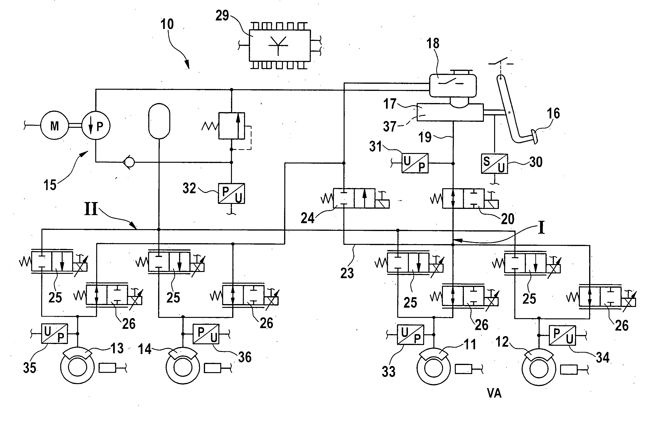
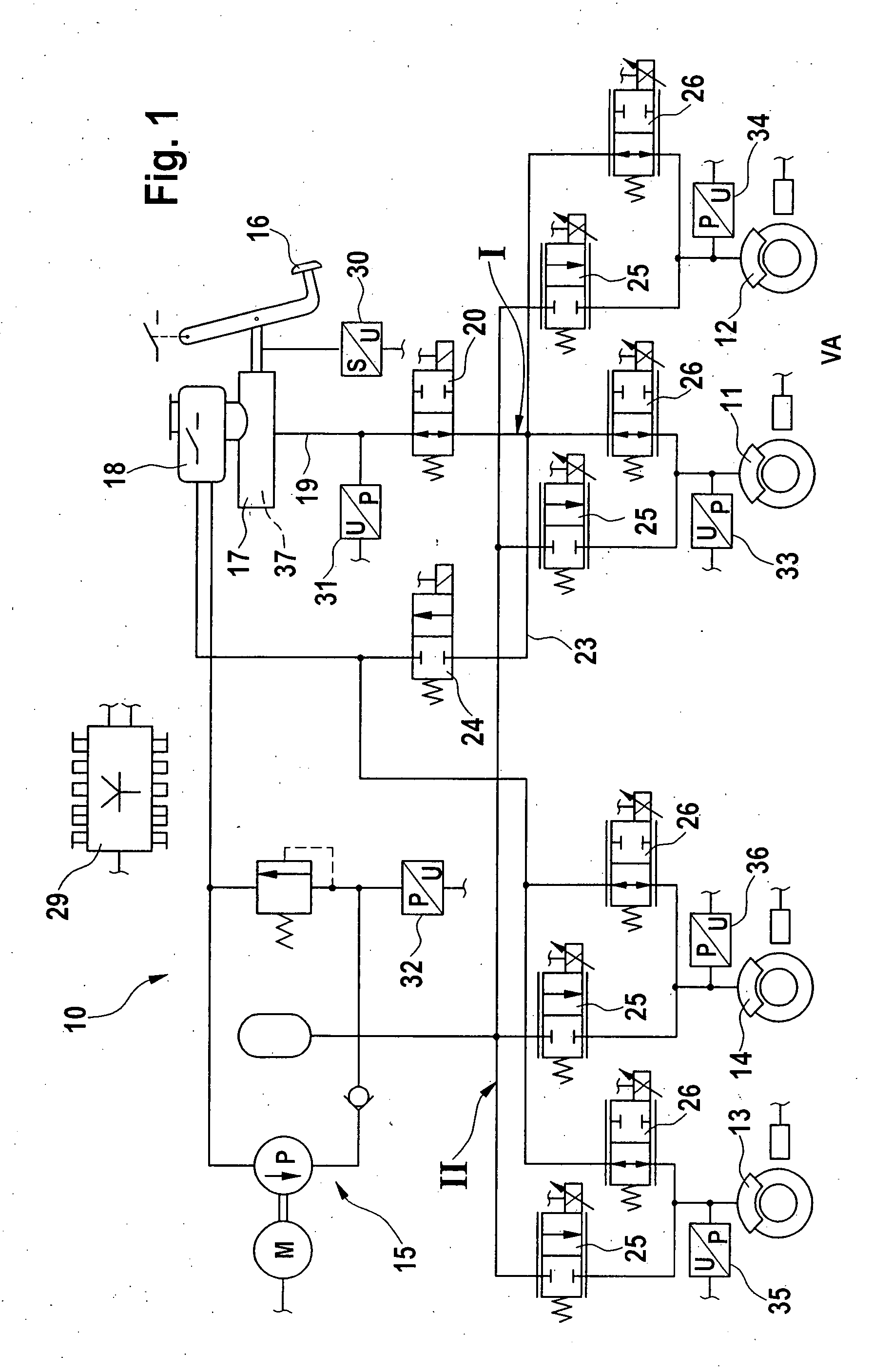
[0013] A power-assisted, hydraulic brake system (wheel brake system) 10 for passenger cars shown in FIG. 1 has a brake circuit I assigned to wheel brakes 11, 12 of front axle FA of the vehicle, and a brake circuit 11 assigned to wheel brakes 13, 14 of rear axle RA. A servo-pressure source 15, which supplies the energy required for the generation of braking force, is connected to both brake circuits I and II. Brake system 10 thus has a service brake, which is activated by external forces. Brake system 10 also includes a secondary brake, which is actuated by muscular energy. It has a main brake cylinder 17, which is actuable by a brake pedal 16 and includes a pressure-medium reservoir 18. Main brake cylinder 17 has a single-circuit design, i.e., it is connected to brake circuit I by a line 19 and a first valve 20 disposed therein. In the illustrated position of valve 20, the secondary brake therefore acts only on wheel brakes 11 and 12 of front axle FA. With an active service brake, v...


PUM


Abstract

A method for operating a brake system of a motor vehicle, prefilling taking place to at least partially overcome an air gap of one wheel brake or a plurality of wheel brakes if the air gap of at least one wheel brake is increased, in particular as a result of dynamic influences of the vehicle motion.

Description

FIELD OF THE INVENTION [0001] The present invention relates to a method, a device and a computer program for operating a brake system of a motor vehicle. BACKGROUND INFORMATION [0002] The function of electronic prefilling of a service brake (electronic brake prefill EBP) overcomes the air gap of the wheel brake by applying the brake linings. Overcoming the air gap reduces the response time of the brake system in a subsequent actuation of the brake pedal. This leads to a shorter pressure-generation time, and thereby shortens the stopping distance. [0003] From German Patent Application No. DE 10 2004 030464, for instance, a brake system having ELB (electronically controlled braking) and prefill function is known as well as a method for electronic brake control. To activate the ELB function in the related art, the accelerator pedal must be released very quickly, from which a possible emergency situation and subsequent panic braking are inferred. The air gap is overcome by an hydraulic ...

Claims


Application Information

Patent Timeline
Patent Type & Authority Applications(United States)
IPC IPC(8): B60T13/66B60T8/17
CPCB60T8/17555B60T8/40Y10T477/813B60T2201/122B60T8/4072
Inventor SCHMIDT, MARIO
Owner ROBERT BOSCH GMBH
Why Eureka
Try Eureka