Method and apparatus for monitoring and controlling density of fractional tissue treatments

a fractional tissue and density technology, applied in the field of fractional tissue density monitoring and controlling treatment density, can solve the problems of uneven treatment, over-treatment, or under-treatment, and not all patients respond the same way to the same level of treatment, so as to promote rapid healing of the wounded area, reduce the intensity of treatment, and increase the size of each treatment zone

Inactive Publication Date: 2008-03-06
RELIANT TECH INC
View PDF99 Cites 95 Cited by
  • Summary
  • Abstract
  • Description
  • Claims
  • Application Information

AI Technical Summary

Benefits of technology

[0026]In another example, the scanning motion of a scanning delivery unit is not changed, but the pulse rate or pulse timing of the electromagnetic source is changed by the controller so as to change treatment density in response to measurements by at least one positional sensor, skin response sensor and/or skin characteristic sensor. Additionally, the pulse timing and scanner patterns can be chosen such that the beam is intentionally dragged across the target region to reduce the treatment intensity and/or to increase the size of each treatment zone created by each energy pulse.
[0027]In fractional treatment, healthy skin is spared in regions between indiv

Problems solved by technology

In many cases, physicians and nurses do not treat uniformly, resulting in uneven treatment, over-treatment, or under-treatment.
However, not all patients respond the same way to the same level of treatment.
Designing for the most sensitive region or patient will frequently lead to under-treatment of other regions or patients.
This type of treatment apparatus is slow and has a lot of repetitive motions, which can be tiring to the operator.
This system requires skill and increases the risks of over- or under-treatment in the hands of an unskilled operator.
Weckwerth U.S. Pat. No. 6,758,845 describes the use of optical measurements of regularly spaced indicia that are placed on or adjacent to the target region, but the concept is limited by the application of regularly spaced indicia that are counted to measure distance traveled

Method used


Image

  • Method and apparatus for monitoring and controlling density of fractional tissue treatments
  • Method and apparatus for monitoring and controlling density of fractional tissue treatments
  • Method and apparatus for monitoring and controlling density of fractional tissue treatments

Examples


Embodiment Construction

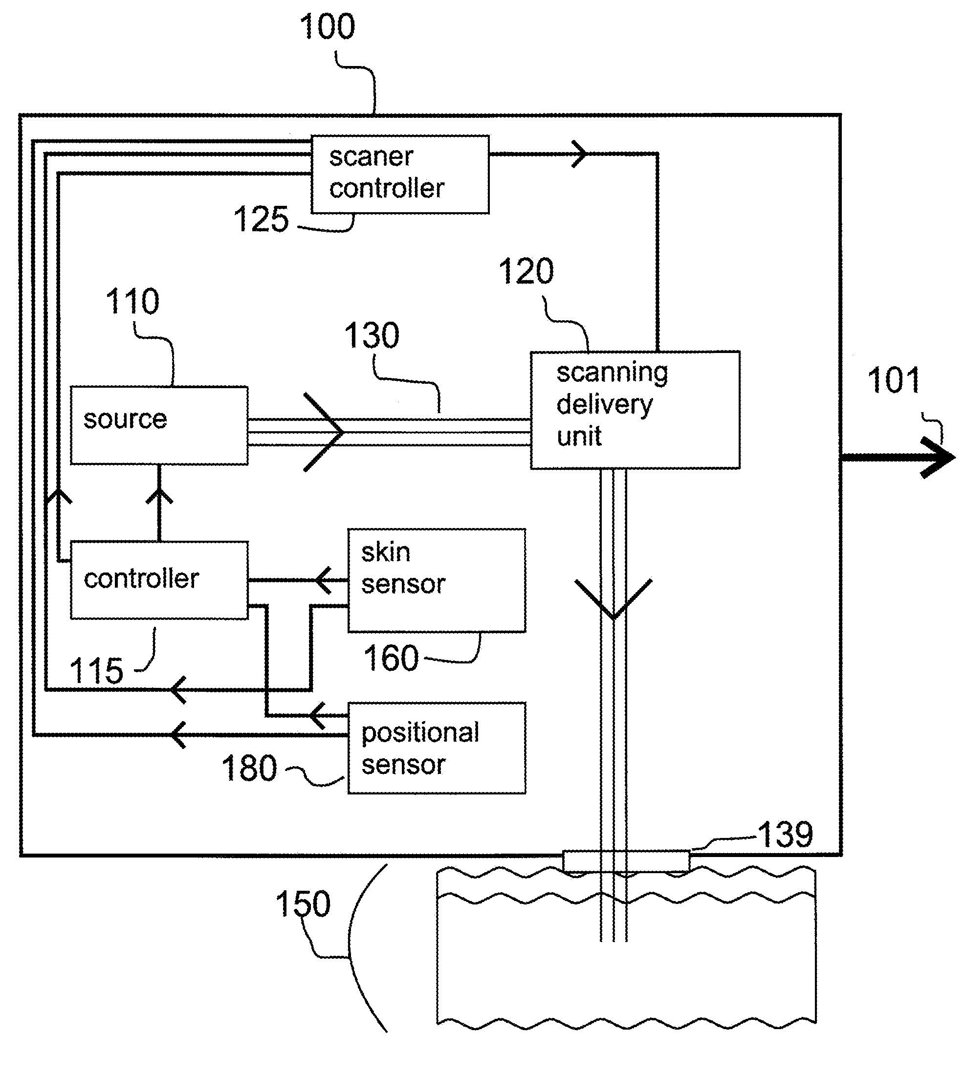
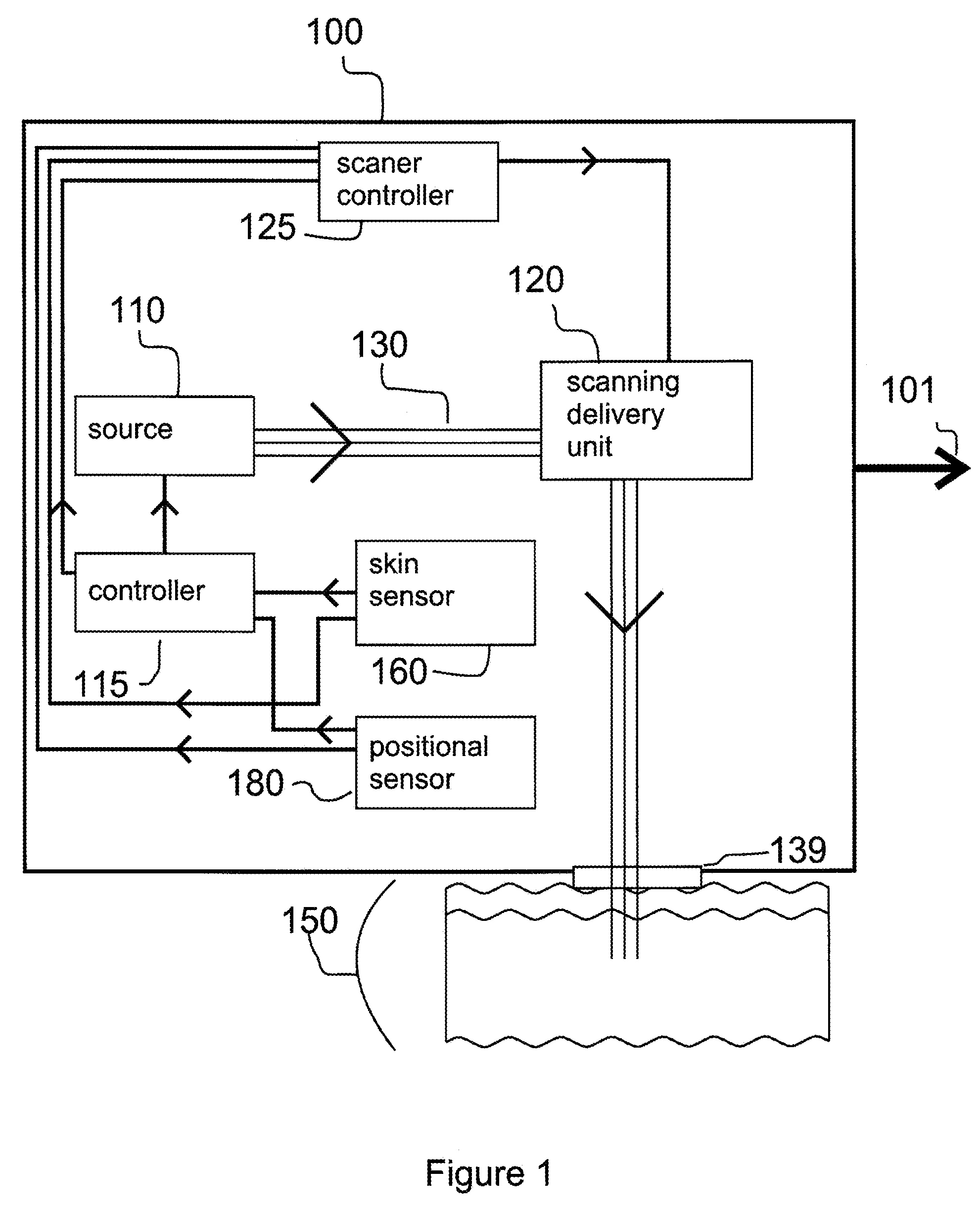
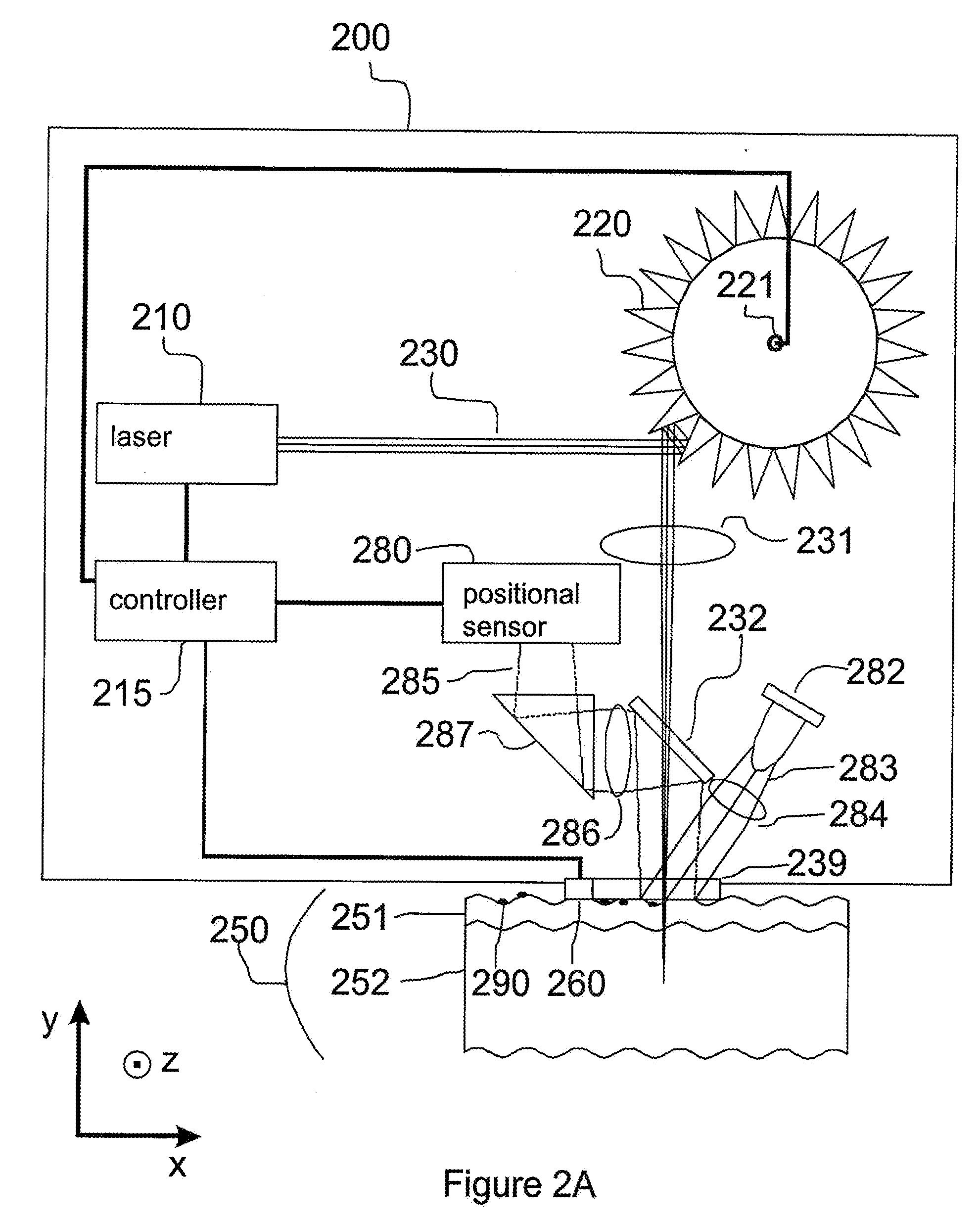
[0041]This invention describes an electromagnetic system with automatic adaptive control of fractional (photothermal and / or RF) treatment density, as well as a method of treating tissue in a fractional manner using an electromagnetic system with automatic adaptive control of treatment density. Treatment density is the number of treatment zones produced per unit surface area in a target region of skin or portion thereof. A nominal pattern and treatment density can be defined when the system begins treatment and this treatment density can be modified based on a measured position of the handpiece, an intrinsic characteristic of the tissue undergoing treatment and / or a change in an intrinsic characteristics of the tissue, a skin response to the treatment and / or a change in a skin response to the treatment. Sensors of various types can be used to determine the measured position parameter, skin characteristic and / or skin response. Algorithms that describe the positional parameter, skin ch...


PUM


Abstract

A method and apparatus for fractional treatment of skin by irradiating the skin with electromagnetic energy is disclosed. Sources of the electromagnetic energy can include radio frequency (RF) generators, lasers, and flashlamps. The apparatus includes at least one sensor configured to detect a positional parameter, a skin characteristic, a skin response, or combinations thereof. The sensor provides feedback to a controller. The controller controls the treatment parameters, including the treatment density. By sensing the positional parameter, skin characteristic and/or skin response to a treatment, the controller automatically adjusts treatment density in real-time in response to the sensed positional parameter, skin characteristic and/or skin response.

Description

CROSS-REFERENCE TO RELATED APPLICATIONS[0001]This application is a continuation-in-part of co-pending U.S. patent application Ser. No. 11 / 468,275, “Method and Apparatus for Monitoring and Controlling Thermally Induced Tissue Treatment,” by Kin F. Chan, George Frangineas, Leonard C. DeBenedictis, and Robert Kehl Sink, Aug. 29, 2006, from which priority is claimed and which is incorporated by reference in its entirety.BACKGROUND OF THE INVENTION[0002]1. Field of the Invention[0003]The present invention relates to a method and apparatus for providing fractional dermatological tissue treatment, and more particularly, to controlling treatment density as provided by an electromagnetic source based on measurements of positional parameters, skin responses, and / or skin characteristics.[0004]2. Description of the Related Art[0005]Many electromagnetic dermatological treatment systems require extensive training before physicians and nurses develop the skills to deliver energy uniformly over a t...

Claims


Application Information

Patent Timeline
IPC IPC(8): A61N5/06A61B18/18
CPCA61B18/20A61B18/203A61B19/5244A61B2017/00106A61B2018/00452A61B2018/00636A61B2019/5458A61B2019/5248A61B2019/5251A61B2019/5255A61B2019/5263A61B2019/5265A61B2018/00642A61B34/20A61B2034/2048A61B2034/2051A61B2034/2055A61B2034/2063A61B2034/2065A61B2090/3958
Inventor FRANGINEAS, GEORGEDEBENEDICTIS, LEONARD C.CHAN, KIN F.SINK, ROBERT KEHL
Owner RELIANT TECH INC
Why Eureka
Try Eureka