Method and Apparatus for Monitoring and Controlling Thermally Induced Tissue Treatment

Inactive Publication Date: 2007-04-26
RELIANT TECH INC
View PDF99 Cites 93 Cited by
  • Summary
  • Abstract
  • Description
  • Claims
  • Application Information

AI Technical Summary

Benefits of technology

[0021] In another embodiment of the invention, the scanning motion of a scanning delivery unit is not changed, but the pulse rate or pulse timing of the electromagnetic source is changed by the controller in response to measurements by at least one positional sensor and/or at least one dosage evaluation sensor. The pulse timing and scanner patterns may be chosen such that the beam is intentionally dragged across the treatment region to reduce the treatment intensity and/or to increase the size of each treatment

Problems solved by technology

In many cases, physicians and nurses do not treat uniformly, resulting in uneven treatment, over treatment, or under treatment.
Additionally, not all patients respond the same way to the same level of treatment.
Designing for the most sensitive region or patient will frequently lead to undertreatment of other regions or patients.
This type of treatment apparatus is slow and has a lot of repetitive motions, which can be tiring to the operator.
This system requires skill and increases the risks of over- or under-treatment in the hands of an unskilled operator.
Weckwerth U.S. Pat. No. 6,758,845 describes the use of optical measurements of regularly spaced indicia that are placed on or adjacent to the treatment region, but the concept is limited by the application of regularly spaced indicia that are counted to measure distance trave

Method used


Image

  • Method and Apparatus for Monitoring and Controlling Thermally Induced Tissue Treatment
  • Method and Apparatus for Monitoring and Controlling Thermally Induced Tissue Treatment
  • Method and Apparatus for Monitoring and Controlling Thermally Induced Tissue Treatment

Examples


Example

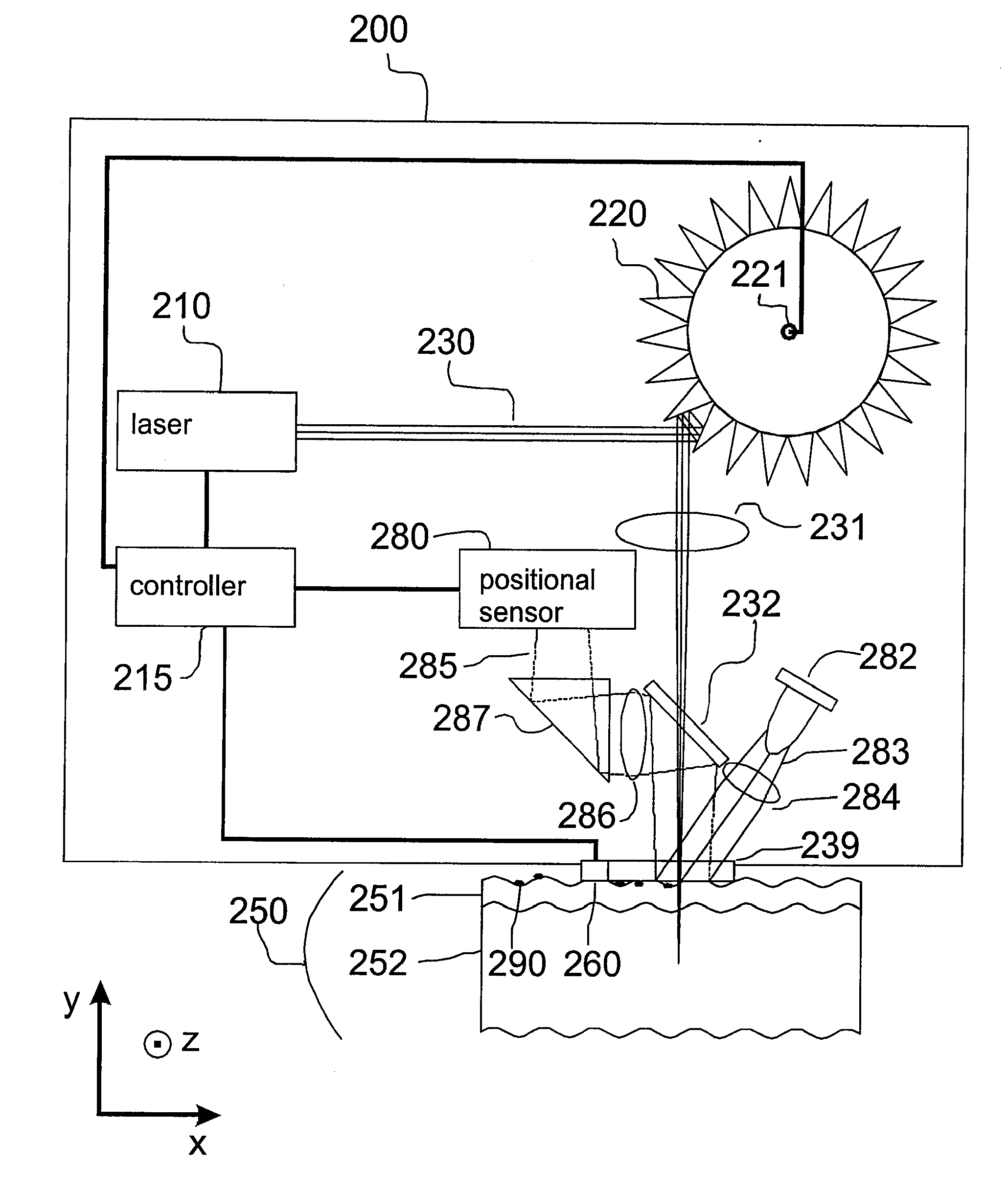
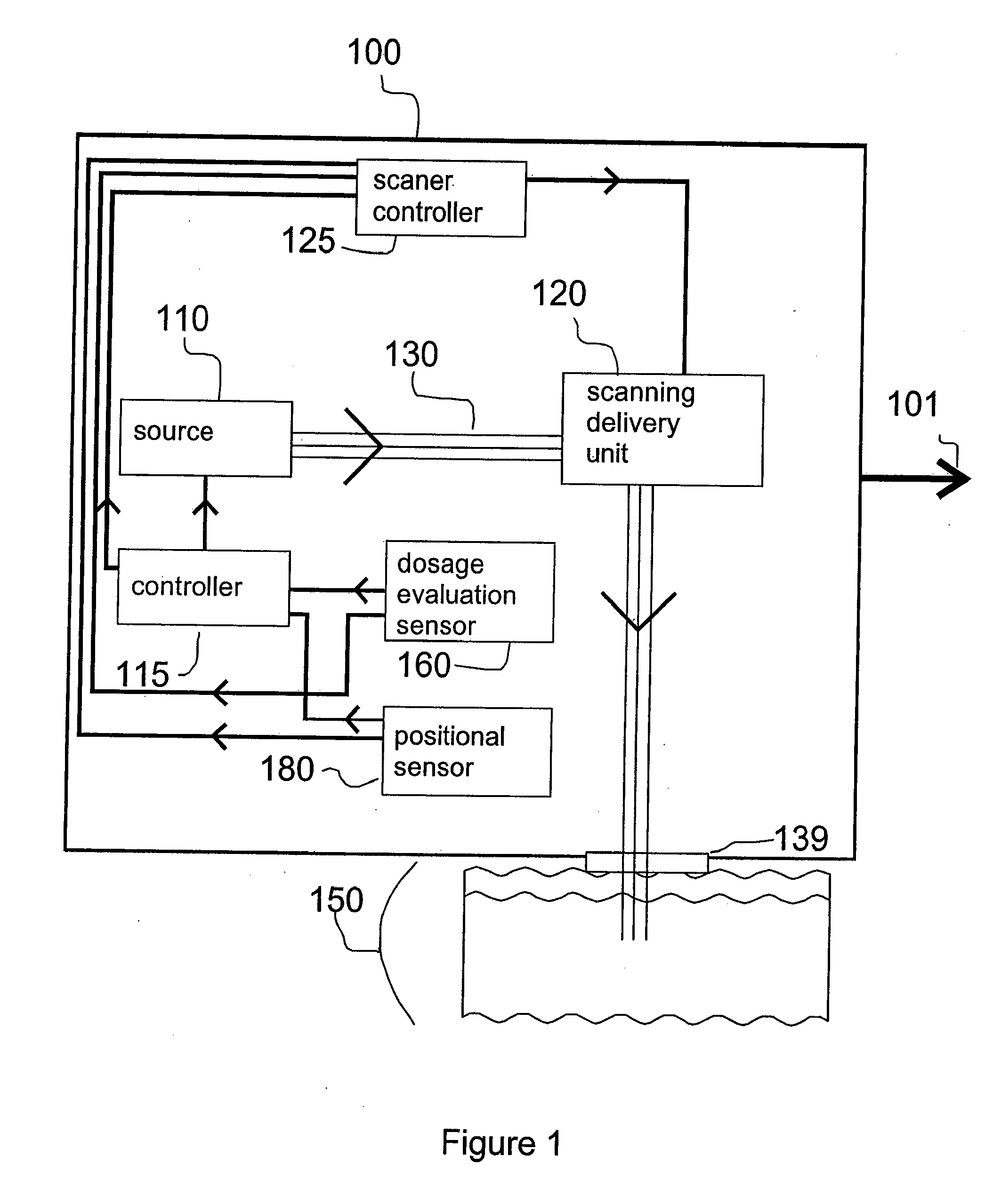
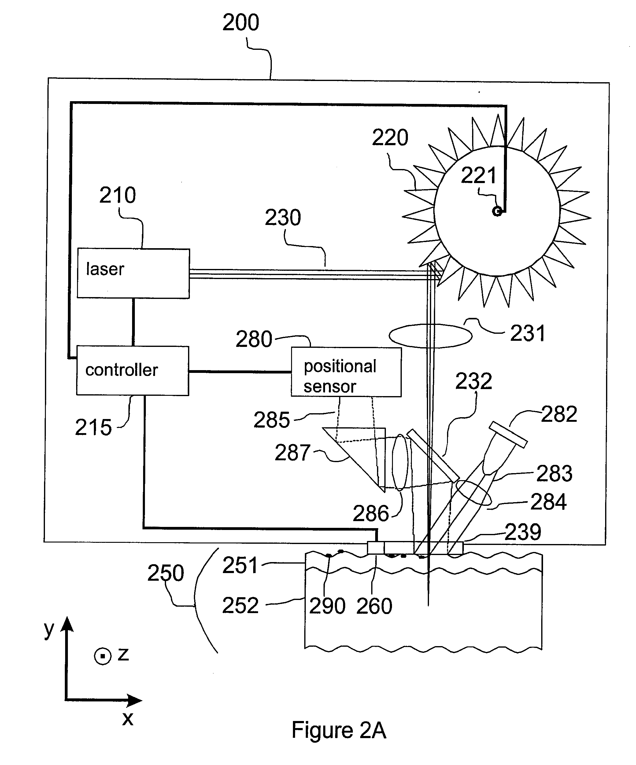
[0037] This invention describes an electromagnetic system with automatic adaptive control of (photothermal and / or RF) treatment parameters and / or activation. A nominal pattern and treatment rate may be defined when the system begins treatment and this treatment pattern can be modified based on algorithms that describe the skin response to treatment and / or the positional parameters of the handpiece. Which positional parameter measurements or skin response measurements are made may depend upon particular measurement results. For example, if the handpiece is moving very rapidly across the skin and treatment power is proportional to relative handpiece speed, then bulk heating of the tissue may be a concern. In this case, the dosage evaluation sensors may be instructed by the controller to measure skin parameters that are associated with blistering due to over treatment. If movement is slow, bulk heating and blistering may be less of a concern and more of the processing power of the cont...


PUM


Abstract

A method and apparatus for thermal treatment of tissue by irradiating the skin with electromagnetic energy is disclosed. Sources of electromagnetic energy include radio frequency (RF) generators, lasers, and flashlamps. The apparatus includes either a positional sensor or a dosage evaluation sensor, or both types of sensors. These sensors provide feedback to a controller. The controller may control the electromagnetic source parameters, the electromagnetic source activation, and/or the sensor measurement parameters. An additional scanning delivery unit may be operably coupled to the controller or to the sensors to provide a controlled distribution of electromagnetic energy to the target region of the skin. The use of positional measurement sensors and dosage evaluation sensors permits the controller to automatically determine the proper electromagnetic source parameters including, for example, pulse timing and pulse frequency.

Description

CROSS-REFERENCE TO RELATED APPLICATIONS [0001] This application claims priority under 35 U.S.C. §119(e) to U.S. Provisional Patent Application Ser. No. 60 / 712,358, “Method and Apparatus for Monitoring and Controlling Thermally Induced Tissue Treatment,” by Leonard C. DeBenedictis, George Frangineas, Kin F. Chan, B. Wayne Stuart III, Robert Kehl Sink, Thomas R. Myers and Basil Hantash, filed Aug. 29, 2005. The subject matter of all of the foregoing is incorporated herein by reference in their entirety.BACKGROUND OF THE INVENTION [0002] 1. Field of the Invention [0003] The present invention relates to a method and apparatus for dermatological tissue treatment, and more particularly, to controlling dosage from an electromagnetic source based on measurements of a handpiece motion and / or skin tissue response. [0004] 2. Description of the Related Art [0005] Many electromagnetic dermatological treatment systems require extensive training before physicians and nurses develop the skills to d...

Claims


Application Information

Patent Timeline
IPC IPC(8): A61B18/18A61N1/00A61N5/06
CPCA61B18/14A61B18/203A61B19/5244A61B2017/00022A61B2017/00106A61B2018/00452A61B2018/00476A61B2019/5231A61B2019/5248A61B2019/5251A61B2019/5255A61B2019/5259A61B2019/5263A61B2019/5265A61B2019/5276A61B2019/545A61B2019/5458A61N5/062A61B34/20A61B2034/2048A61B2034/2051A61B2034/2055A61B2034/2059A61B2034/2063A61B2034/2065A61B2090/373A61B2090/378A61B2090/395A61B2090/3958
Inventor DEBENEDICTIS, LEONARD C.CHAN, KIN F.STUART, B. WAYNE IIIMYERS, THOMAS R.SINK, ROBERT KEHLHANTASH, BASIL M.STUMPP, OLIVER
Owner RELIANT TECH INC
Why Eureka
Try Eureka