Electronic Motor

Inactive Publication Date: 2008-03-13
SCHLUMBERGER TECH CORP
View PDF23 Cites 34 Cited by
  • Summary
  • Abstract
  • Description
  • Claims
  • Application Information

AI Technical Summary

Benefits of technology

[0014]In one preferred embodiment, the sub-shafts are connected by means of homocinetic couplings such that the instantaneous angle between the rotor and its associated stator is substantially identical for each motor sub-unit. The control systems are typically arranged to drive the phases of the motor sub-units together.
[0015]The stator windings can be provided in a variety of configurations and the control system arranged to

Problems solved by technology

A significant limitation concerning the use of electric motors is the limited diameter (OD) available for them to be fitted into downhole equipment, and consequently their limited volume.
Current electric motor technology therefore provides a limit to the maximum power that can be provided within this limited volume.
There are also thermal limitations for electric motors, the cooling capability mostly being proportional to the external surface of the stator (convection with the well fluid is often the predominant mechanism for heat transfer).
For conventional electric motors used in the oilfield industries (the rotor being internal and the stator being wound internally), winding becomes very challenging when the length of the stator exceeds three times its OD.
This can result in difficulty in ensuring a proper manufacturing process and for proper inspection of the inner winding for a long stator.

Method used


Image

  • Electronic Motor
  • Electronic Motor

Examples


Embodiment Construction

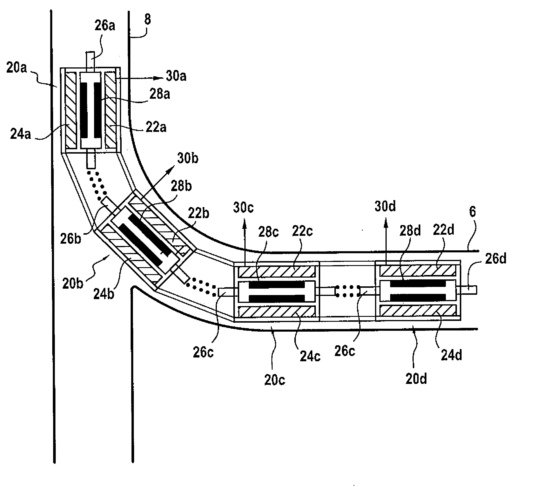
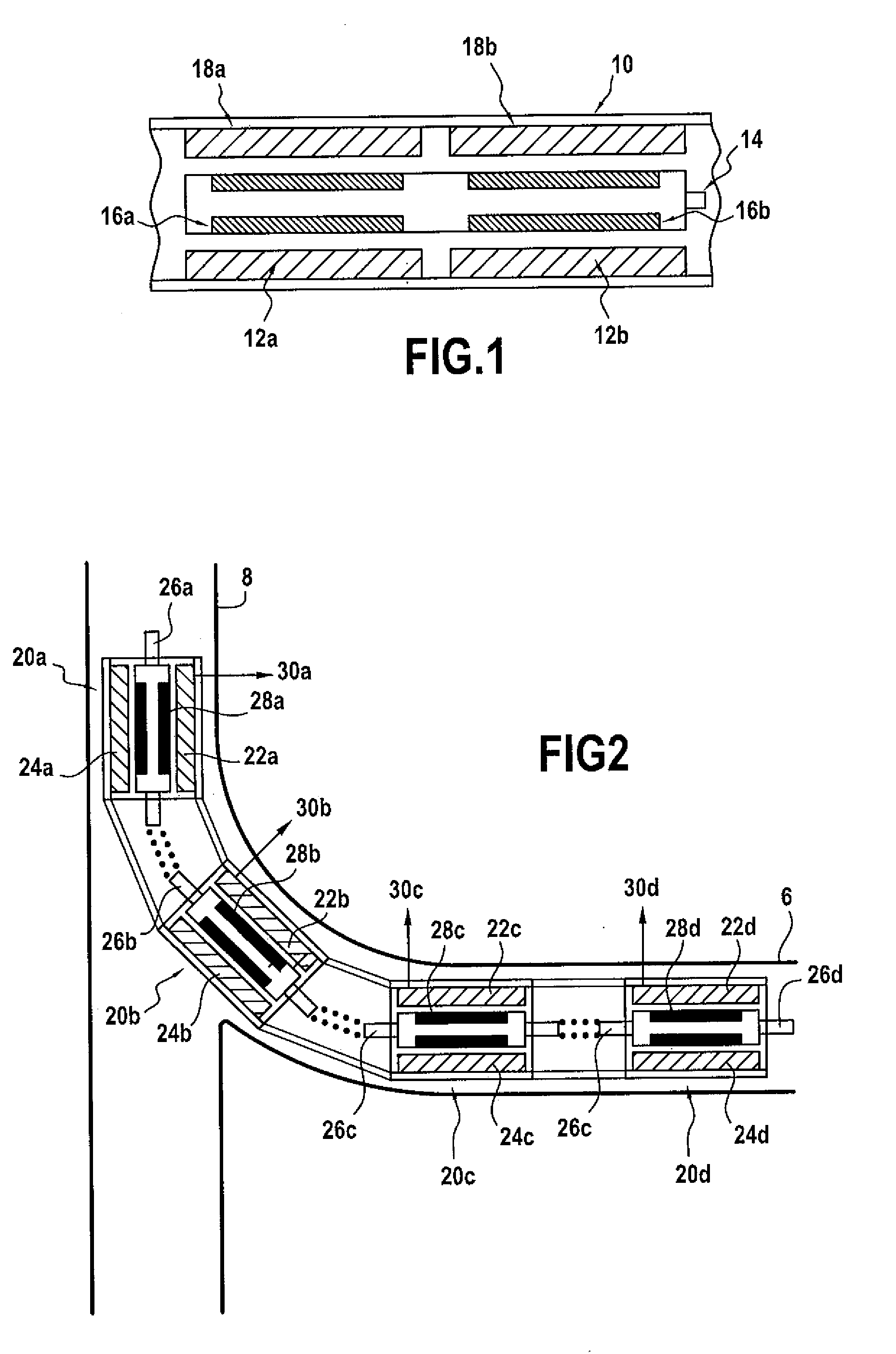
[0020]FIG. 1 shows a schematic view of part of a motor section of a borehole tool such as a drilling tool for drilling lateral boreholes. The motor comprises a cylindrical housing 10 of normal size for placement in a borehole. Stator windings 12a, 12b are provided inside the housing 10, spaced apart in the axial direction. An output shaft 14 is mounted for rotation inside the housing so as to be coaxial with the stators 12a, 12b. Rotors 16a, 16b are mounted on the output shaft 14 and positioned to align with the stator windings 12a, 12b so as to define motor sub-units. Each sub-unit is connected to a respective power supply and control system 18a, 18b. One particularly preferred form of motor sub-unit is formed from stators and rotors of the type used in conventional motors for borehole tools. Such motors are commonly synchronous brushless motors which are preferred for their great power density and high reliability, but other forms of motor such as asynchronous AC motors and DC mot...


PUM


Abstract

An electric motor for use in a borehole tool, comprising: a housing; a plurality of stator windings spaced along the inside of the housing; an output shaft located in the housing; a plurality of rotors disposed on the output shaft and aligned with the stators so as to define a plurality of motor sub-units; and separate power supplies and control systems for each motor sub-unit; wherein each motor sub-unit is separately controllable by means of its associated power supply and control system. The output shaft can comprise a single shaft with the rotors disposed thereon or a plurality of sub-shafts connected end to end with each rotor can be disposed on an associated sub-shaft. The sub-shafts can connected by means of articulated connections, and the housing can be articulated in the region of the connections.

Description

TECHNICAL FIELD [0001]This invention relates to electric motors and specifically to their use in downhole tools such as are used in exploration and production of hydrocarbons.BACKGROUND ART [0002]Electric motors are widely used in downhole equipment in the hydrocarbon exploration and production industries. Such motors can be powered via cable from the surface, downhole generators powered by fluid flow, or batteries. A significant limitation concerning the use of electric motors is the limited diameter (OD) available for them to be fitted into downhole equipment, and consequently their limited volume. Current electric motor technology therefore provides a limit to the maximum power that can be provided within this limited volume. There are also thermal limitations for electric motors, the cooling capability mostly being proportional to the external surface of the stator (convection with the well fluid is often the predominant mechanism for heat transfer). Consequently for a given rat...

Claims


Application Information

Patent Timeline
IPC IPC(8): H02K16/00
CPCE21B4/04F04D13/10H02K16/00H02K7/003H02K5/132
Inventor SCHMITT, BENOIT
Owner SCHLUMBERGER TECH CORP
Why Eureka
Try Eureka