
Moving object locating apparatus

a moving object and locating technology, applied in direction finders using radio waves, instruments, reradiation, etc., can solve the problems of inability to operate properly, ineffectiveness of conventional pet search systems, and often run out of batteries on target units, etc., to prolong the standby time of the apparatus, increase product endurance, and save significant energy

Inactive Publication Date: 2008-03-13
HUANG DENNIS
View PDF6 Cites 24 Cited by
  • Summary
  • Abstract
  • Description
  • Claims
  • Application Information

AI Technical Summary

Benefits of technology

[0014]The detection activating device sends out an alert by beeping, flashing, vibrating or other means that provide equivalent effects to notify the user. Also with the sound strength of the alarm, the user is able to locate the moving object more efficiently.
[0018]Prior to reception of any searching signal, the target unit remains in the standby mode. The target unit in the present invention is configured to switch on the power and transmit response signals only upon reception of the searching signals, which ultimately saves significant energy, increases product endurance and extends the standby time of the apparatus.

Problems solved by technology

In practice, however, the conventional pet search systems are ineffective in finding the lost pet since the target unit that is placed on a pet keeps sending signals to the search unit and consumes power regardless of whether the pet is lost.
Therefore, if the pet actually goes missing, the batteries on the target unit have often run out and as a result cannot be operated properly.
Also, the search unit in the conventional pet search systems is provided only with a single antenna for transmitting and receiving signals, which in fact is insufficient to accurately locate the position of the lost pet, and the pet owner often will not be able to retrieve the lost pet.

Method used


Image

  • Moving object locating apparatus
  • Moving object locating apparatus
  • Moving object locating apparatus

Examples


Embodiment Construction

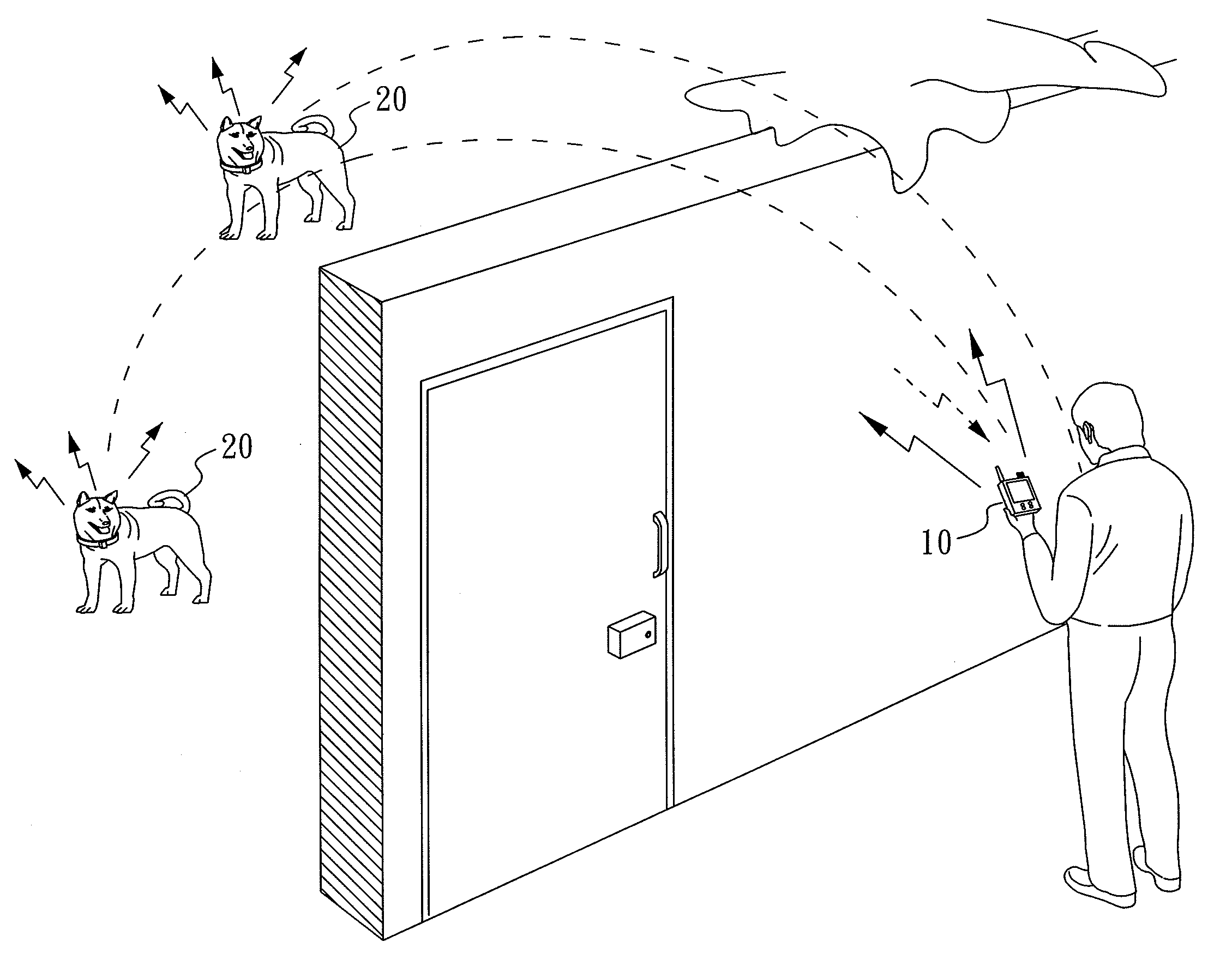
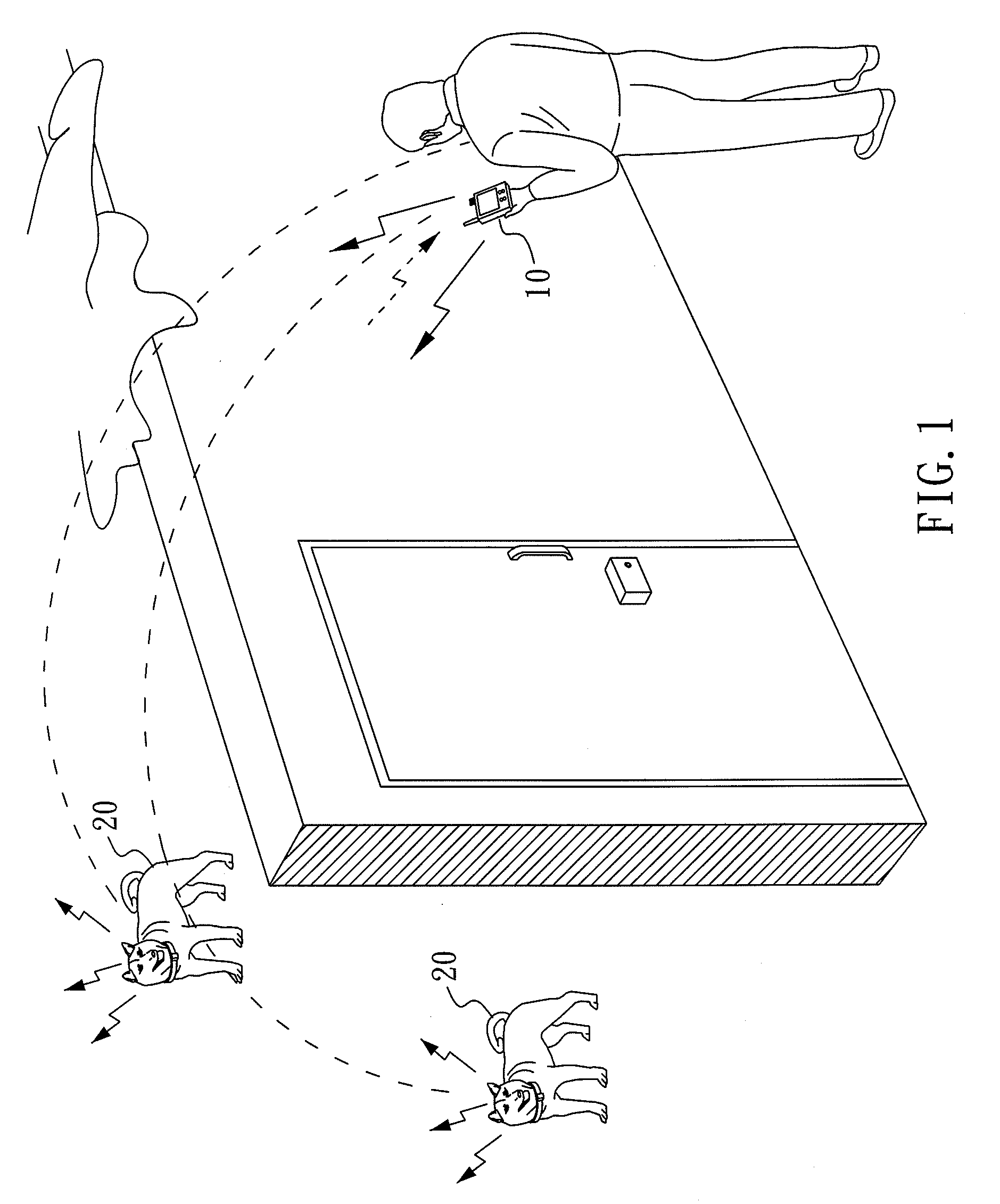
[0023]Referring to FIG. 1, which shows the structure and the components therein of the present invention, a moving object locating apparatus comprises a search unit 10 and at least one target unit 20. The search unit 10 can be assigned to one target unit 20 or can be assigned to a plurality of target units 20. FIG. 1, as an example, illustrates a search unit 10 being assigned to two target units 20.

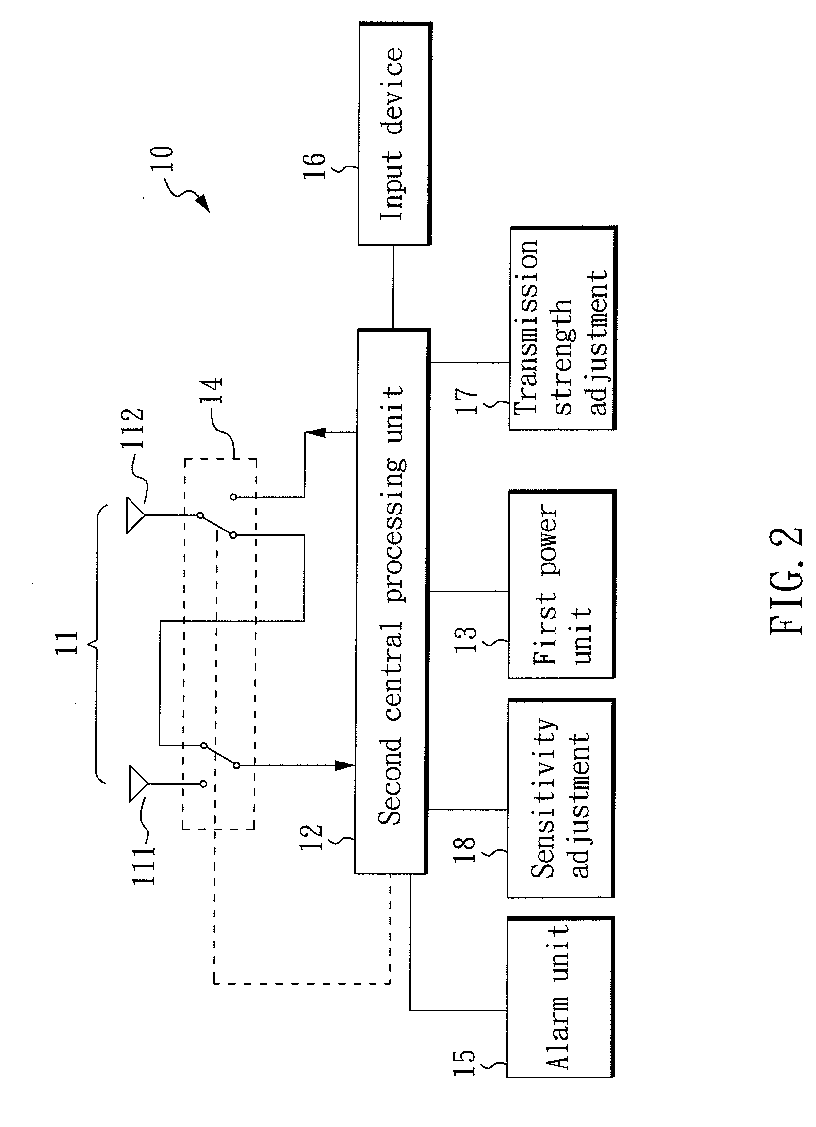
[0024]Referring to FIG. 2, the search unit 10 of the present invention mainly comprises an antenna module 11, a first central processing unit 12 and a first power unit 13. The first central processing unit 12 carries out a coding process, and a search signal that contains an identification code is transmitted through the antenna module 11. The search unit 10 further comprises an input device 16 that permits inputting of identification numbers. For the convenience of the user to adjust the transmission strength and the reception sensitivity, the search unit 10 further comprises a transmiss...


PUM


Abstract

The present invention relates to a moving object locating apparatus that comprises a search unit and at least one target unit. The first central processing unit is configured to proceed with coding, and the antenna module is configured to transmit searching signals that carry identification codes. The target unit, which is provided with a default identification code, comprises a radio transmit-receive unit, a second central processing unit and a second power unit. When the radio transmit-receive unit receives the searching signal, the second central processing unit will decode the identification code carried by the searching signal and matches with the default identification code of the target unit. When two codes are matched, the second central processing unit then will proceed to coding and then actuate the radio transmit-receive unit to transmit a response signal, which carries the default identification code, back to the search unit.

Description

BACKGROUND OF THE INVENTION[0001]1. Field of the Invention[0002]The present invention relates to a moving object locating apparatus and, more particularly, to a moving object locating apparatus having an omni-directional antenna along with a directional antenna.[0003]2. Description of Related Art[0004]Most of the conventional pet search systems comprise of a search unit and a target unit. The target unit is mounted on a pet, such that whenever a pet goes missing or moves beyond the pet owner's sight, the pet owner can utilize the search unit by sending out a searching signal. Upon receiving the searching signal, the target unit will respond with a response signal that permits the pet owner to retrieve the lost pet.[0005]In practice, however, the conventional pet search systems are ineffective in finding the lost pet since the target unit that is placed on a pet keeps sending signals to the search unit and consumes power regardless of whether the pet is lost. Therefore, if the pet ac...

Claims


Application Information

Patent Timeline
Patent Type & Authority Applications(United States)
IPC IPC(8): G08B13/14G08B1/08G08B23/00G08B5/22
CPCA01K11/006A01K15/021G08B21/02G01S3/06G01S3/38A01K29/00G01S13/74G01S13/825G08B21/24
Inventor HUANG, DENNIS
Owner HUANG DENNIS
Learn More