Apparatus for separating workpieces

a workpiece and apparatus technology, applied in metal-working apparatus, de-stacking articles, thin material processing, etc., can solve the problems of inability to achieve desired separation, insufficient achievable cycle output for modern machining devices, and limited efficiency of systems, so as to reduce the energy input required, save considerable amounts of energy, and control the negative pressure operation of the suction device

Active Publication Date: 2018-11-01
HOMAG GMBH
View PDF1 Cites 0 Cited by
  • Summary
  • Abstract
  • Description
  • Claims
  • Application Information

AI Technical Summary

Benefits of technology

[0022]According to a development of the invention, it is further provided that the suction device has a negative pressure line with a closing device by means of which the negative pressure supply in the negative pressure line can be at least partially interrupted. This makes it possible to control the negative pressure operation of the suction device particularly precisely and at the same time save considerable amounts of energy. For example, the negative pressure supply can be interrupted by the closing device if no specific workpiece is to be discharged or separated by means of said discharge device.
[0023]In this case, it is particularly preferable that the closing device is synchronised with the feed device. As a result, the energy input required can be minimised with a reliable mode of operation. In this case, it is particularly preferable that the closing device is actuated by the feed device. As a result, both design and also control of the apparatus according to the invention can be simplified considerably.

Problems solved by technology

However, with relatively thin workpieces that are unstable under bending, like panels, such systems have proven to be of only limited efficiency.
The achievable cycle output is not generally adequate for modern machining devices in which panels are conveyed at very high machining speeds.
However, the difficulty which arises with this system is that, in addition to the lowest workpiece, the adjacent workpiece is also discharged so that the desired separation cannot be achieved.

Method used


Image

  • Apparatus for separating workpieces
  • Apparatus for separating workpieces
  • Apparatus for separating workpieces

Examples


Embodiment Construction

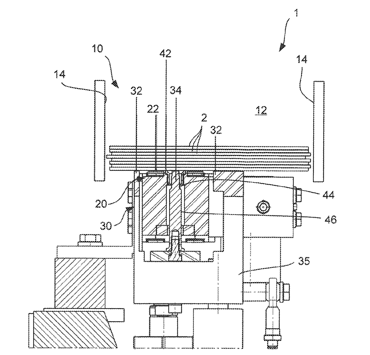
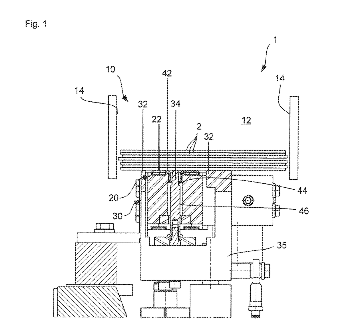
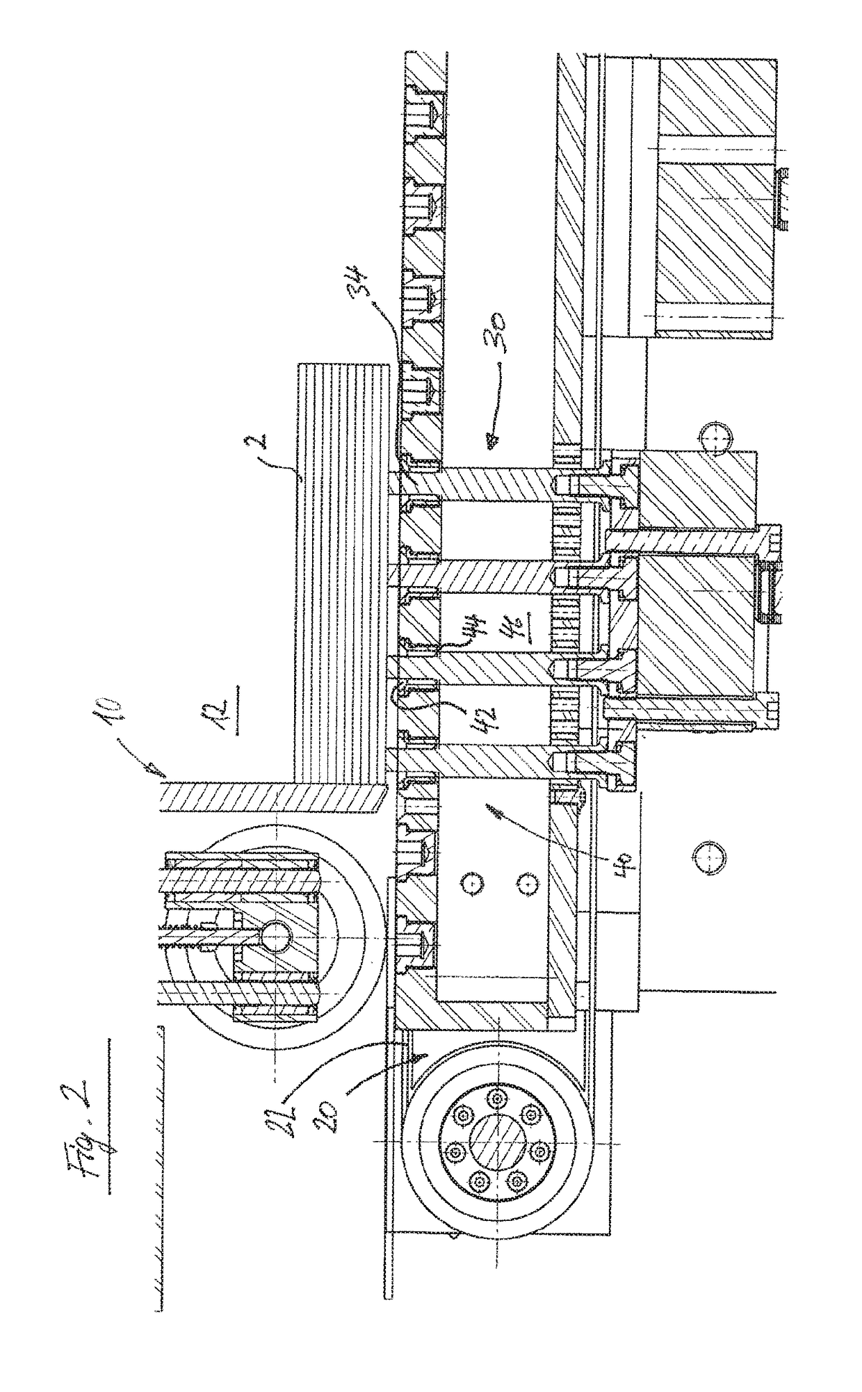
[0046]Preferred embodiments of the invention will be described in the following with reference to the associated drawings.

[0047]An apparatus 1 for separating workpieces according to a preferred embodiment of the invention is illustrated schematically in various sectional views in FIGS. 1 to 3. The apparatus 1 is used to separate workpieces 2 which can consist, for example, of wood, wood-based materials, plastic or the like. The apparatus 1 is particularly suitable for comparatively flexible workpieces, such as panels for covering floors or walls in particular. However, in principle any workpieces can be separated.

[0048]Although not shown in the figures, the separating apparatus 1 can advantageously be part of a machining device for machining workpieces, said machining device having, for example, a milling unit, drilling unit, sawing unit or a variety of other machining units.

[0049]The separating apparatus 1 initially has a workpiece magazine 10, a stack of workpieces 2 being arrange...


PUM


Abstract

Apparatus for separating workpieces which preferably consist at least in sections of wood, wood-based materials, plastic or the like, having a workpiece magazine with a magazine area for holding a plurality of workpieces, in particular a stack of workpieces, a discharge device for discharging a workpiece out of the workpiece magazine, characterised in that the apparatus has a feed device which is set up to feed at least one workpiece held in the workpiece magazine to the discharge device.

Description

CROSS-REFERENCE TO RELATED APPLICATIONS[0001]This application claims priority under 35 U.S.C. § 119 to German Patent Application DE102017207004.8, filed on Apr. 26, 2017, the disclosure of which is incorporated herein by reference in its entirety.TECHNICAL FIELD[0002]The invention relates to an apparatus for separating workpieces which preferably consist at least in sections of wood, wood-based materials, plastic or the like, according to the preamble of claim 1.PRIOR ART[0003]In the area of the wood processing industry, workpieces are often provided in stacks in order to be fed subsequently to a machining apparatus and machined therein. Panels, such as are used for example as wall or floor covering, can be mentioned as examples.[0004]The workpiece stacks are usually kept in a workpiece magazine and pushed individually out of the workpiece magazine by means of a discharge device. Cams or sliders, for example, can be used for this purpose.[0005]However, with relatively thin workpiece...

Claims


Application Information

Patent Timeline
Patent Type & Authority Applications(United States)
IPC IPC(8): B23Q7/14B23Q7/00B27M1/08
CPCB23Q7/1447B23Q7/005B27M1/08B23P19/004B23Q7/00B23Q7/06B65G59/06B65H3/042B65H3/34B65H3/54B65H2701/1938
Inventor WINNEY, STEPHENMUELLER, MICHAELSTEEB, MARCELTHUMM, MICHAEL
Owner HOMAG GMBH
Why Eureka
Try Eureka