Angular diversity antenna system and feed assembly for same

a technology of antenna system and feed assembly, applied in the field of communication system, can solve the problems of unreliable use of troposcatter communication link, loss of signal, and fading of signals by as much as twenty or more decibels, and achieve the effect of angular diversity in the antenna system, cost-effectiveness, and convenient deploymen

Active Publication Date: 2008-03-13
CPI SATCOM & ANTENNA TECH INC
View PDF6 Cites 20 Cited by
  • Summary
  • Abstract
  • Description
  • Claims
  • Application Information

AI Technical Summary

Benefits of technology

[0013]Accordingly, it is an advantage of the present invention that a feed assembly for an antenna system is provided.
[0014]It is another advantage of the present invention that a dual-beam feed assembly is provided that achieves angular diversity in an antenna system without performance compromise.
[0015]Another advantage of the present invention is that a dual-beam feed assembly is provided that enables a tropospheric scatter system to be implemented as a cost effective, transportable, and readily deployable system.
[0016]The above and other advantages of the present invention are carried out in one form by a feed assembly for an antenna system. The feed assembly includes a first feed element exhibiting an elongated conical shape having a first apex and a first aperture at the first apex. The first feed element propagates a first beam. A second feed element is collocated with the first feed element, the second feed element exhibiting the elongated conical shape having a second apex and a second aperture at the second apex. The second feed element propagates a second beam, and the first and second beams are substantially non-overlapping.
[0017]The above and other advantages of the present invention are carried out in another form by a tropospheric scatter communication system having angular diversity. The tropospheric scatter communication system includes a reflector and a feed assembly in communication with the reflector. The feed assembly includes a first feed element exhibiting an elongated conical shape having a first apex and a first aperture at the first apex. The first feed element propagates a first beam over a Ku-band toward the reflector. A second feed element is collocated with the first feed element. The second feed element exhibits the elongated conical shape having a second apex and a second aperture at the second apex. The second feed element propagates a second beam over the Ku-band toward the reflector. The first and second beams are substantially non-overlapping.

Problems solved by technology

Due to both long- and short-term random tropospheric irregularities, rapid variations in received power from the scatter volume can result in signal “fades” by as much as twenty or more decibels.
Deep fades can occur beyond the minimum threshold of the receiver causing a loss of signal and making the use of a troposcatter communication link unreliable.
Unfortunately, the use of two antennas (i.e., two feeds and two reflectors) at each side of a tropospheric link is undesirably costly, complex, time consuming to set up and point the antennas, and utilizes an undesirably large footprint.
Angular diversity is used less than spatial diversity due to the problem of optimizing the diversity angle, which depends on the distance between the two receiving feeds.
Unfortunately, antenna gain is simultaneously reduced because of defocusing at large diversity angles.
Consequently, angular diversity with large diversity angles has only been practical with large diameter antenna reflectors (for example, greater than ten feet) in order to provide sufficient gain and other radio frequency properties.
Unfortunately, relatively high coupling loss between the antenna reflector and the feeds and other distortions result because the dual feeds must compromise their horn design in order to fit within the focal point of the antenna reflector.
However, such large diameter conical or corrugated feed horns grossly overlap each other when positioned at the focal point of the antenna reflector.
Consequently, compromises must be made in the size and shape of the feed horns that result in significant coupling losses and other issues.

Method used


Image

  • Angular diversity antenna system and feed assembly for same
  • Angular diversity antenna system and feed assembly for same
  • Angular diversity antenna system and feed assembly for same

Examples


Embodiment Construction

[0028]The present invention entails a dual-beam feed assembly for an antenna system. In a preferred embodiment, the dual-beam feed assembly is utilized in a tropospheric scatter communication system to provide angular diversity. However, the dual-beam feed assembly described herein may alternatively be used for line of sight (LOS) applications and / or satellite communication (satcom) links. Furthermore, the dual-beam feed assembly is described in connection with a parabolic reflector antenna system. However, the dual-beam feed assembly may alternatively be utilized in connection with other antenna systems, such as a parabolic torus antenna system, a spherical antenna system, a ring focus antenna system, and the like.

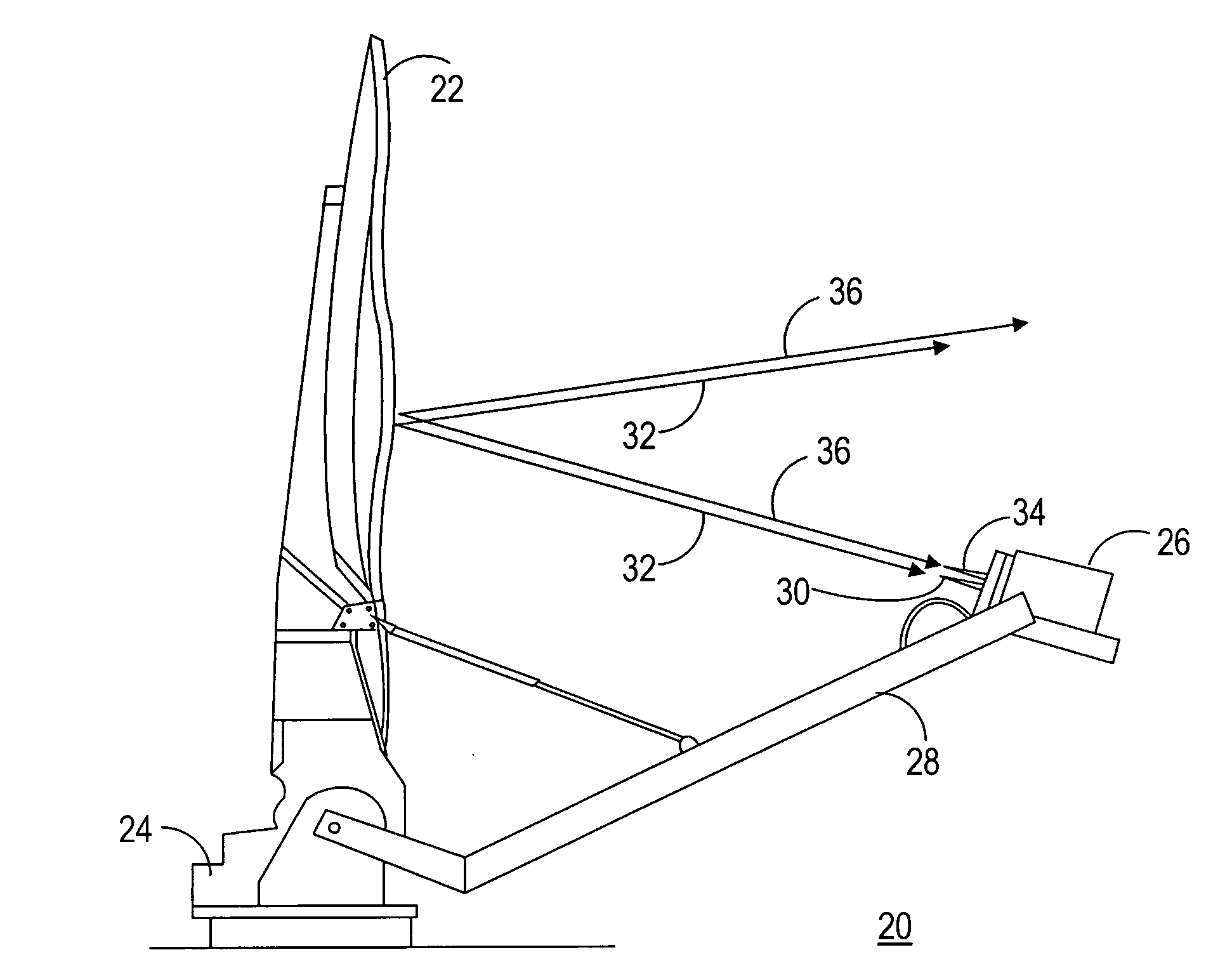
[0029]FIG. 1 shows a side view of a troposcatter station 20 in accordance with a preferred embodiment of the present invention. Troposcatter station 20 includes an antenna reflector 22 mounted on a positioning system 24. A feed assembly 26 is in communication with reflect...


PUM


Abstract

A feed assembly (26) for an antenna system (38) includes a first feed element (30) that propagates a first beam (32) and a second feed element (34) that propagates a second beam (36). The second feed element (34) is collocated with, but displaced vertically from, the first feed element (30) to achieve angular diversity in elevation. Each of the feed elements (30, 34) has an elongated conical shape and is formed from a dielectric material. The feed assembly (26) operates within the Ku-band frequency range to yield high gain, collimated, independent first and second beams (32, 34). The feed assembly (26) can be implemented in a tropospheric scatter communication system (38) in conjunction with a reflector (22) to provide concurrent transmit and receive capability via the two independent, angularly separated first and second beams (32, 36).

Description

TECHNICAL FIELD OF THE INVENTION[0001]The present invention relates to the field of communication systems. More specifically, the present invention relates to a tropospheric scatter communication system having angular diversity.BACKGROUND OF THE INVENTION[0002]It is known that radio waves transmitted towards the horizon can be weakly received beyond the horizon due to an apparent reflective / diffractive nature of the troposphere. The troposphere is the layer of the earth's atmosphere from the ground to a height of approximately eight to ten kilometers (twenty-six thousand to thirty-two thousand feed). The scattering of radio waves off the troposphere, known as tropospheric scatter or troposcatter, has been utilized for commercial applications, normally on frequencies above 500 MHz for over the horizon links, and for transportable / temporary military and strategic communication systems. Troposcatter is advantageous for remote telemetry, or other links where low to medium rate data need...

Claims


Application Information

Patent Timeline
Patent Type & Authority Applications(United States)
IPC IPC(8): H01Q13/00
CPCH01P1/161H01Q25/007H01Q19/17H01Q13/24
Inventor HOFERER, ROBERT A.
Owner CPI SATCOM & ANTENNA TECH INC
Why Eureka
Try Eureka