Method And Apparatus For Locally Measuring Refractive Characteristics Of A Lens In One Or Several Specific Points Of Said Lens

a technology for local measurement and refractive characteristics, which is applied in the field of measuring optical lenses, can solve the problems of affecting the profitability or quality of the work carried out, the apparatus cannot be delegated, and the prescription of the lens is missing, so as to achieve the effect of reducing the cost of the equipment, saving resources, and avoiding the loss of the lens prescription

Inactive Publication Date: 2008-03-13
ESSILOR INT CIE GEN DOPTIQUE
View PDF7 Cites 15 Cited by
  • Summary
  • Abstract
  • Description
  • Claims
  • Application Information

AI Technical Summary

Benefits of technology

[0019] An object of the present invention is to provide a method and apparatus for measuring refractive characteristics as an alternative to existing methods and apparatuses, making it possible to perform local measurements on a lens at specific points thereof in a manner that is fast and accurate, while saving on the hardware resources implemented. Another object of the invention is to make such measurement automatic.
[0033] By selecting which light rays are detached, the position of the measurement axis can thus be modified on each measurement so as to coincide, at least approximately, with the position of the measurement point under consideration on the lens. The measurement as performed in this way focuses on a narrow field around one or more measurement axes that are movable or variable. This combined feature of a measurement field that is both narrow and movable distinguishes the method of the invention fundamentally from mapping type measurement using a field that is wide together with multiple stationary measurement axes. This thus obtains the advantages of targeted measurement: a combination of accuracy together with parsimonious requirements for resources. In particular, identification to distinguish ray impacts on the projection screen can be performed in simple and fast manner, insofar as it is implemented on a small number of rays over a small area. Furthermore, unlike prior art apparatuses having a narrow field and a stationary measurement axis, such as frontofocometers, the measurement axis is not frozen. The measurement axis can be moved by selecting appropriate rays for passing through the point of the lens where it is desired to make a measurement.
[0034] This thus achieves the versatility in measurement of a mapping apparatus. However, by restricting deflection measurements to the vicinity of the point of interest, there is no need to measure all of the other points of the lens that are useless, and there is no need to compute the map of levels or points over the entire lens, nor is there the technical problem of identifying ray impacts. This thus saves on resources that are expensive in terms of measurement and computation while improving the accuracy of the final measurement at the specific point of interest.

Problems solved by technology

It can also happen that the envelope bearing the prescription of a lens is missing, for example when it is desired to discover or verify the characteristics of a lens that has already been mounted or prepared for mounting.
However taking a measurement is relatively lengthy and it cannot be delegated, without risk of error, to an operator having lesser qualifications or who is a beginner.
The use of that apparatus thus tends to impact on the profitability or the quality of the work carried out by an optician.
It will be understood that under such conditions, using apparatus of that kind requires manipulations to be performed that take time and that lead to inaccuracy in the event of the measurement point of the lens not being positioned with precision on the measurement axis of the apparatus.
Under such conditions, it can immediately be seen that that apparatus presents limits and drawbacks.
Its field of application is restricted to single-vision lenses and under no circumstances does it make it possible to measure the refractive characteristics of a lens at points other than its geometrical center, without moving the lens and the associated loss of time and risk of error that such manipulation engenders, as mentioned above for frontofocometers.
However they do not give entire satisfaction when used for measuring refractive characteristics at a small number of specific points of the lens, mainly because of their lack of accuracy, their slowness, and their expense.
The mapping feature of the measurement also implies, for electronic processing of the measurement, large memory requirements for storing the complete map of the lens, long calculation time for drawing up the map, and deflection-measuring means that are complex or inaccurate, since such measurement means ought to perform accurate measurements of all points of the lens simultaneously.
The Applicant has observed that most of the points measured are not useful in verifying the prescription characteristics of an ophthalmic lens.
In particular there is an identification problem of distinguishing between the various points of impact of the light rays on the projection screen, in order to associate each of them individually with the rays from which they are derived, and in spite of the large number and the closeness of ray impact points on the projection screen.
Solving this identification problem requires specific identification means to be implemented which, in order to be reliable, turn out to be relatively complex, to consume large amounts of resources (processor time in particular), and to be expensive.
Unfortunately, having beam separator elements (patterns, microlenses, etc.) that are close together leads firstly to an increased amount of computation, and secondly to worsening the identification problem, so that solving it then requires more complex identification means to be implemented.

Method used


Image

  • Method And Apparatus For Locally Measuring Refractive Characteristics Of A Lens In One Or Several Specific Points Of Said Lens
  • Method And Apparatus For Locally Measuring Refractive Characteristics Of A Lens In One Or Several Specific Points Of Said Lens
  • Method And Apparatus For Locally Measuring Refractive Characteristics Of A Lens In One Or Several Specific Points Of Said Lens

Examples


Embodiment Construction

[0049] The following description with reference to the accompanying drawings of an embodiment given by way of non-limiting example makes it possible to understand what the invention consists in and how it can be implemented.

[0050] In the accompanying drawings:

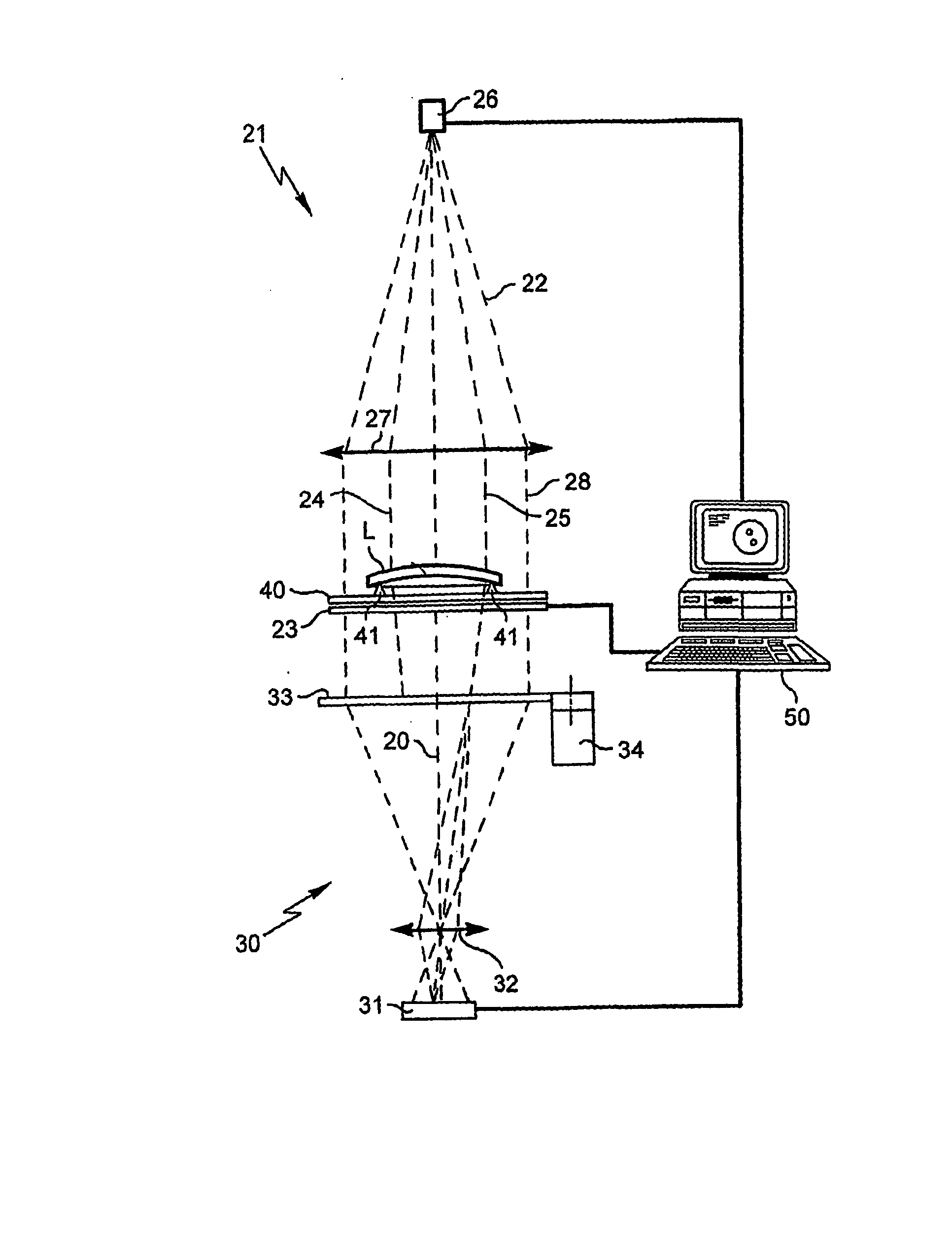
[0051]FIG. 1 is an overall diagrammatic view of apparatus of the invention for measuring the refractive characteristics of a lens;

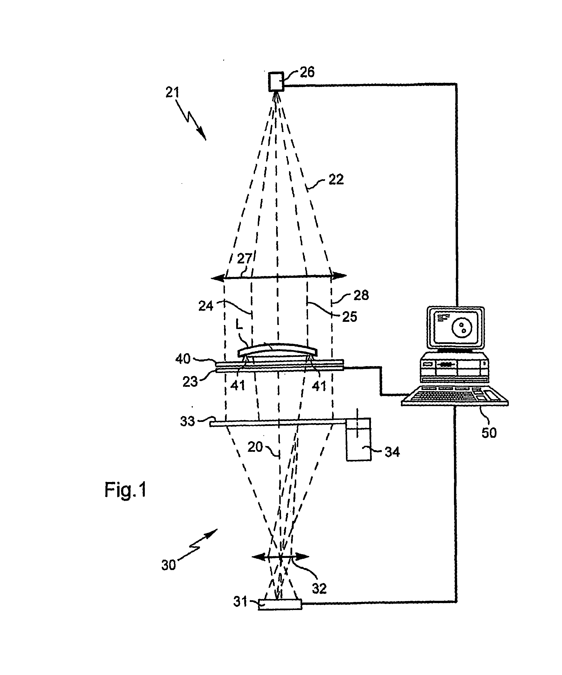
[0052]FIG. 2 is a plan view of the active mask on its own, implemented in the form of an LCD graphics screen;

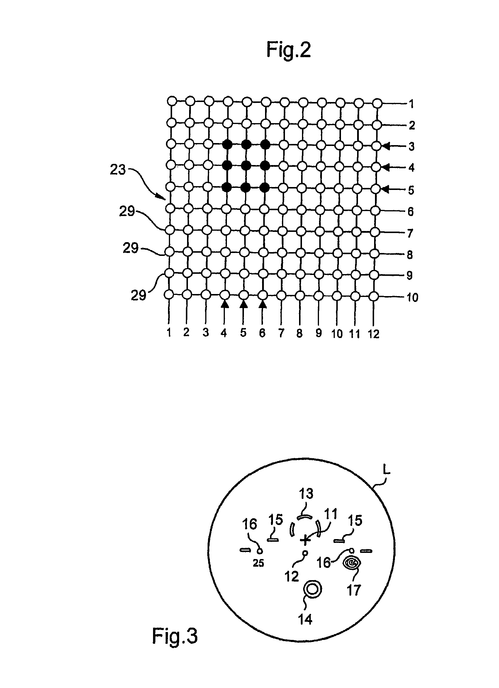
[0053]FIG. 3 is a plan view of the front face of a progressive correcting lens showing the conventional marking of said lens;

[0054]FIG. 4 is a plan view of the FIG. 3 lens which, after being placed in the measurement apparatus, is superposed on the active mask with a group of light rays pointed at and concentrated around the reference point for far vision being detached by activating corresponding pixels of the LCD mask;

[0055]FIG. 5 is a perspective view in a configuration analogous to t...


PUM


Abstract

The measurement apparatus includes: a support arranged to receive a lens; lighting element including an optical system for generating a collimated light beam directed towards the lens under measurement installed on the support; detachment elements for detaching light rays from the light beam, for detaching a localized group of at least three non-coplanar light rays grouped together about a measurement axis in a measurement cylinder of section substantially smaller than the section of the lens under measurement; acquisition elements for identifying the deflections imparted by the lens on the detached light rays and for delivering a signal representative of the deflections; and an electronic and computer system programmed to deduce from said deflections the value of the refractive characteristic of the lens at the measurement point.

Description

TECHNICAL FIELD TO WHICH THE INVENTION APPLIES [0001] The present invention relates in general to measuring an optical lens such as an ophthalmic lens of a pair of correcting eyeglasses, and it relates more particularly to apparatus for measuring refractive characteristics of such a lens at one or more specific or determined points of said lens. TECHNOLOGICAL BACKGROUND [0002] Before mounting a pair of ophthalmic lenses for correcting eyeglasses in a frame, an optician generally seeks to verify that the main optical characteristics of the lenses, and in particular their refractive characteristics, at one or more points do indeed correspond to the prescription for which they were ordered. At present, this can consist, for example, in verifying the spherical, cylindrical, and prismatic powers and the cylindrical and prismatic orientations at one or more prescribed points. When the prescribed lens is a single-vision lens, the prescribed point where measurement is to be performed is the...

Claims


Application Information

Patent Timeline
Patent Type & Authority Applications(United States)
IPC IPC(8): G01B9/00
CPCG01M11/0228
Inventor DIVO, FABIENTHEPOT, JAMES
Owner ESSILOR INT CIE GEN DOPTIQUE
Why Eureka
Try Eureka