
Method and system for controlled fusion reactions

a fusion reaction and controlled technology, applied in nuclear reactors, nuclear engineering, greenhouse gas reduction, etc., can solve the problems of limited success in creating an efficient, self-sustaining fusion reaction, serious hydrodynamic instability, and limited prior approaches, so as to reduce the number of beams used to illuminate the target, reduce the cost and size of the reactor, and increase the reliability

Active Publication Date: 2008-03-13
ADVANCED FUSION SYST LLC
View PDF91 Cites 54 Cited by
  • Summary
  • Abstract
  • Description
  • Claims
  • Application Information

AI Technical Summary

Benefits of technology

[0014] The foregoing embodiment increases efficiency of a fusion power system by extracting both high voltage DC energy and thermal energy.
[0018] The foregoing embodiment of the invention has the ability to produce an RF heating pulse simultaneously with the x-ray drive pulse without reducing efficiency. This allows the use of RE heating to increase the efficiency of the fusion power system at little additional cost and with no energy penalty.
[0020] The foregoing embodiment of the invention corrects the wavefront errors that give rise to Rayleigh-Taylor Hydrodynamic Instability by means of the mentioned Apodizing Filter. As the target pellet is a sphere, the Apodizing filter is used to change the shape of the compression wavefront to a highly concave surface whose radius matches the radius of the target. By this means, the wavefront “wraps around” one face of the target and provides totally uniform compression of the target.
[0021] A direct benefit of the use of Apodizing Filters to correct the compression wavefront is that the number of beams used to illuminate the target is reduced. Instead of the 192 beams that the National Ignition Facility Fusion Reactor at Lawrence Livermore lab in California uses, the current embodiment of the invention may allow the use of as far fewer beams, such as 6. This directly reduces the cost and size of the reactor, while increasing its reliability.

Problems solved by technology

However, despite billions of dollars invested, only limited success has been achieved in creating an efficient, self-sustaining fusion reaction.
All prior approaches have been limited by three major factors: (a) Only a singe means of energy extraction is used.
(c) Hydrodynamic Instability is a serious problem.
This occurs when the compression of the target pellet is not sufficiently uniform.
It gives rise to local thermal non-uniformity which, in turn, causes local cooling.
This results in an unsymmetrical burn of the fuel.
The disadvantage of this technique to prior art fusion power systems is that it produces high voltage DC.
High voltage DC is difficult to work with and, more importantly, not suitable for long distance power transmission and distribution.
It cannot be readily or efficiently shifted in voltage as AC power can.
Hydrodynamic Instability is a major problem that the designer of every fusion power system faces.
Formally known as Rayleigh-Taylor Instability, it is a problem that arises from non-uniform compression of the fuel pellet.
Non-uniformities in excess of 1% in compression result in the formation of ‘jets’ of energy that surge outward and locally cool the target pellet.

Method used


Image

  • Method and system for controlled fusion reactions
  • Method and system for controlled fusion reactions
  • Method and system for controlled fusion reactions

Examples


Embodiment Construction

[0038] A list of drawing reference numbers' their associated parts and preferred materials for the parts can be found near the end of this description of the preferred embodiments. Literature references are cited in full after the list of drawing reference numbers. In this description, short literature references for author “Nakai,” for instance, are given as follows: (Nakai Reference.)

Main Principles of Preferred Embodiments

[0039] Main principles of preferred embodiments of the invention are described in connection with FIGS. 1-3.

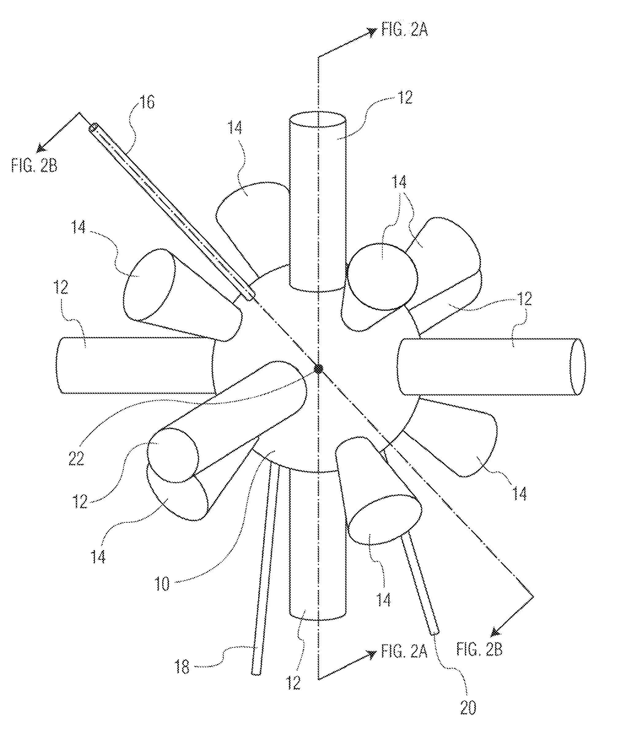
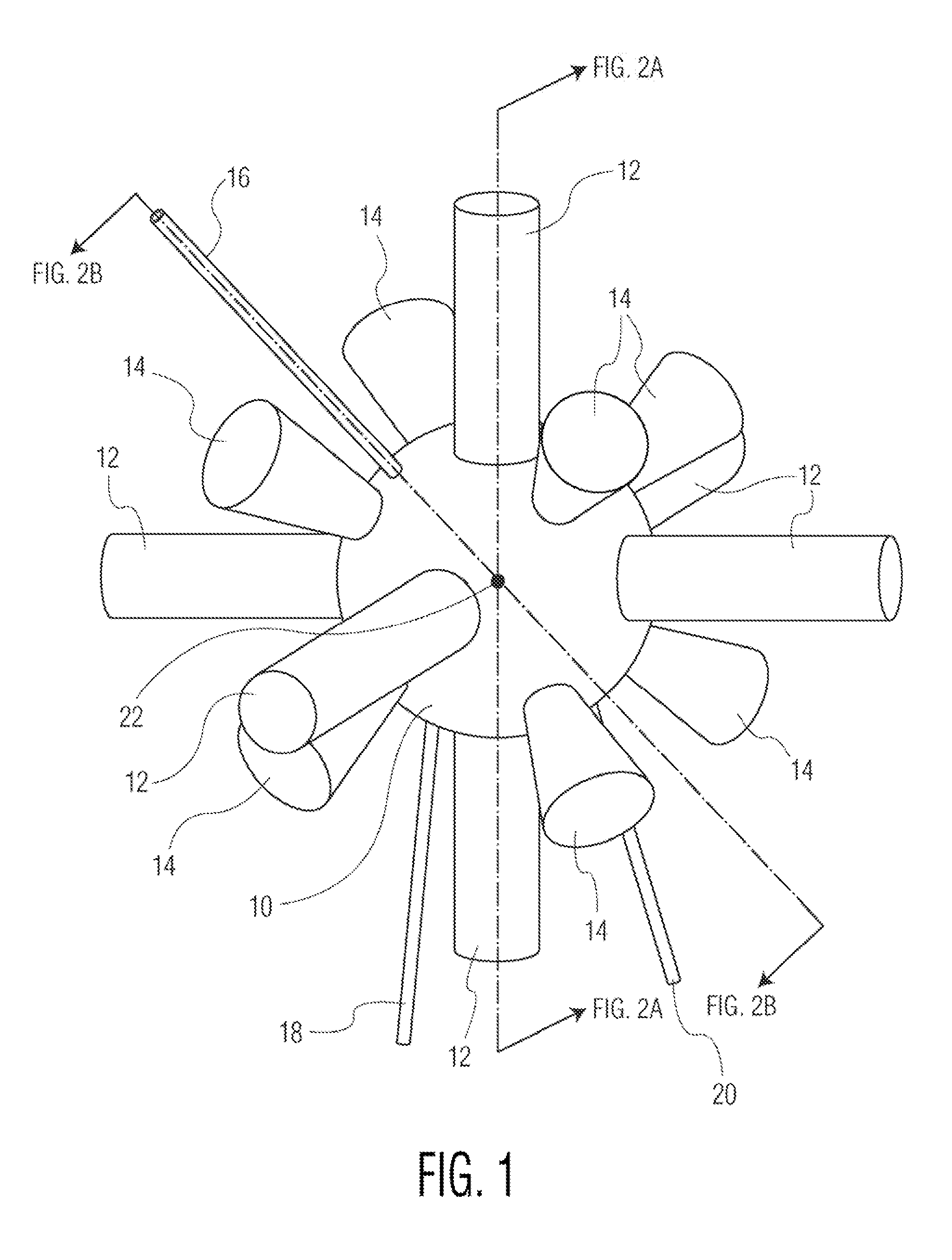
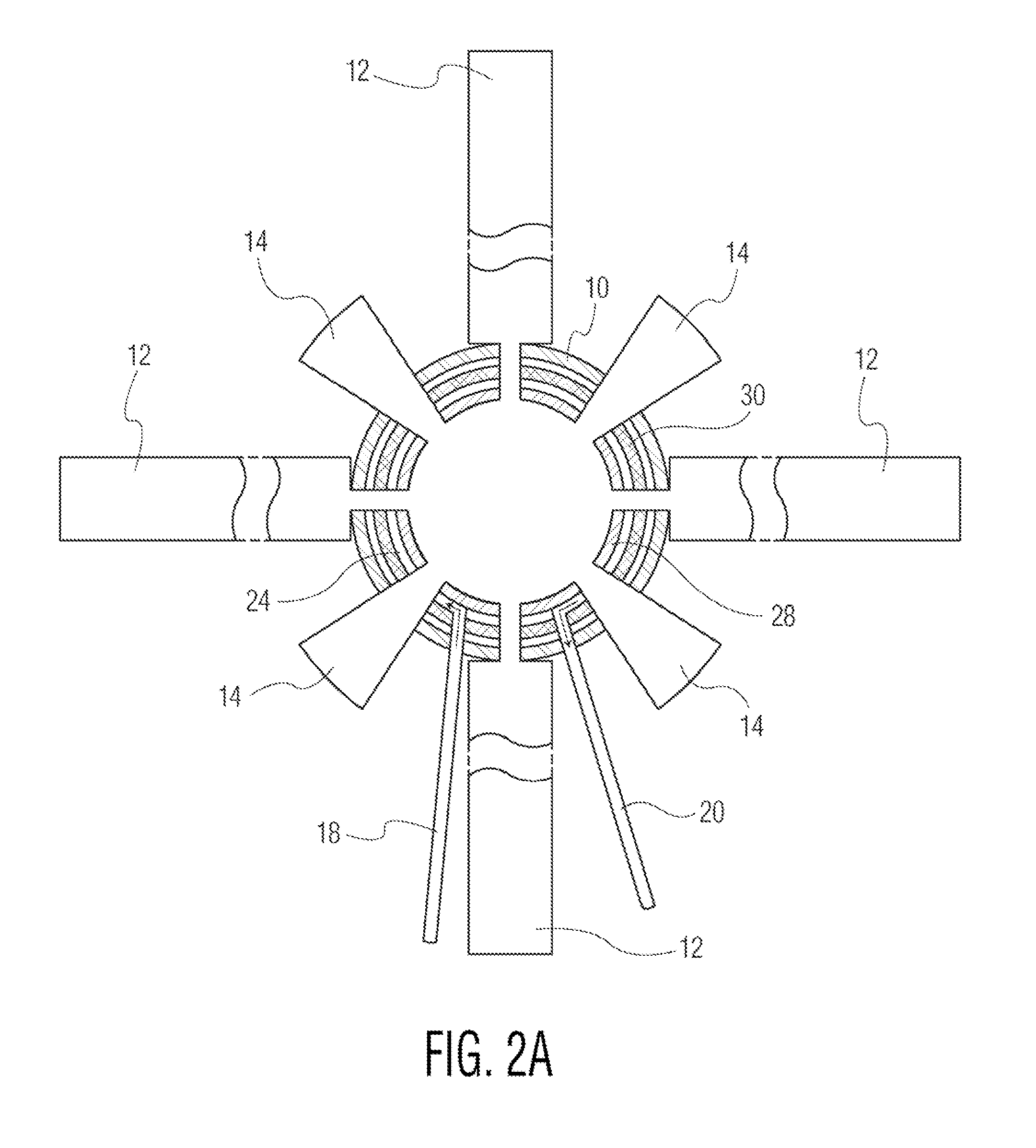
[0040]FIG. 1 shows a reactor for generation of energy by controlled nuclear fusion. The system includes of a central target chamber or region 10. A series six or more of Energy Drivers 12 are arranged in symmetrical pairs around the central target region. The symmetrical Energy Drivers 12 are arranged in symmetrical manner about a target pellet location 22, so as to collectively create a preferably highly spherical wavefront that impinges on target fusi...


PUM


Abstract

Disclosed is a system for extracting energy from controlled fusion reactions. The system includes a central target chamber for receiving fusion target material. A plurality of energy drivers are arranged around the target chamber so as to supply energy to fusion target material in the chamber to initiate a controlled fusion reaction of the materials releasing energy in the forms of fusion plasma and heat. A plurality of structures for extracting energy from the fusion reaction are provided, and comprise devices to extract high voltage DC power from the fusion plasma; and means to extract thermal energy from the central target chamber. Power to the energy drivers may be supplied from high voltage DC power extracted from the fusion reactions. The energy drivers may use an Apodizing filter to impart a desired shape to the wavefront of the driving energy for causing the fusion reactions, to avoid hydrodynamic instabilities.

Description

PRIORITY APPLICATION [0001] This application claims priority from U.S. Provisional Patent Application No. 60 / 809,453 entitled “Method & Apparatus for Controlled Fusion Reactions” filed May 26, 2006. The foregoing application is incorporated herein by reference in its entirety.FIELD OF THE INVENTION [0002] The present invention relates to methods and systems for extracting energy from controlled fusion reactions. BACKGROUND OF THE INVENTION [0003] It is widely recognized that controlled fusion offers a clean and plentiful energy source. However, despite billions of dollars invested, only limited success has been achieved in creating an efficient, self-sustaining fusion reaction. All prior approaches have been limited by three major factors: [0004] (a) Only a singe means of energy extraction is used. [0005] (b) Instead of focusing on Direct Drive X-ray driven reactions, the bulk of the work has been focused on indirect drive reactions, particularly using large lasers as drivers. [0006...

Claims


Application Information

Patent Timeline
IPC IPC(8): G21B1/00
CPCG21B1/03G21B1/23G21B1/00Y02E30/14H01F38/00G21D7/00H05G2/001Y02E30/10Y02E30/00G21B3/008H05G2/00G21B1/11
Inventor BIRNBACH, CURTIS A.
Owner ADVANCED FUSION SYST LLC
Learn More