
Sample analyzer and its components

a sample analyzer and sample technology, applied in the field of sample analyzers, can solve the problems of inability to immediately obtain the results of blood analysis in an emergency case, prone to remain negative pressure in the vacuum blood sampling tube, complicated etc., to reduce the size and weight of the analyzer, simplify the operation of the sample analyzer, and facilitate the handling of the analyzer

Active Publication Date: 2008-03-13
SYSMEX CORP
View PDF5 Cites 5 Cited by
  • Summary
  • Abstract
  • Description
  • Claims
  • Application Information

AI Technical Summary

Benefits of technology

The present invention aims to simplify the operation of a sample analyzer for easy handling by doctors and nurses, reduce the size and weight of the analyzer for easy transportation to diagnostic and medical treatment sites, suppress the noises of the analyzer for a quieter environment, and ensure safe and easy maintenance and inspection of the analyzer. The invention achieves these objectives by providing a liquid aspirator for easy handling, a preparing section for preparing an analysis sample using a sample, a analyzing section for analyzing the prepared analysis sample, and an air bubble detector for ensuring accurate results. Additionally, the invention provides a sample analyzer comprising a liquid transfer unit for transferring liquids to the detector.

Problems solved by technology

In addition, the operation of the blood analyzers is complicated, so that special operators should be employed as regular staff.
However, it is impossible to immediately obtain the results of blood analyses in an emergency case.
However, in the case of this system, when the pipette is inserted in a vacuum blood sampling tube (a rubber-capped tube) employed as a sample container, a negative pressure is liable to remain in the vacuum blood sampling tube.
Accordingly, the sucking operation of the suction device is not smoothly performed, resulting in erroneous quantification.
Thus, there is a problem that the analysis of the sample cannot be performed accurately.
On the other hand, if a conventional vent pipe is attached to the pipette in parallel, the analyzer needs to further provide a cleaning flow system for cleaning the vent pipe, so that the construction of the analyzer is complicated.

Method used


Image

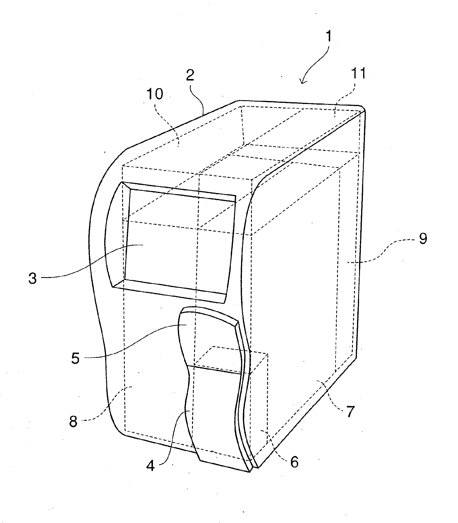
  • Sample analyzer and its components
  • Sample analyzer and its components
  • Sample analyzer and its components

Examples


example

[0113] With reference to the attached drawings, this invention will hereinafter be described in detail by way of another embodiment thereof. However, it should be understood that the invention be not limited thereto.

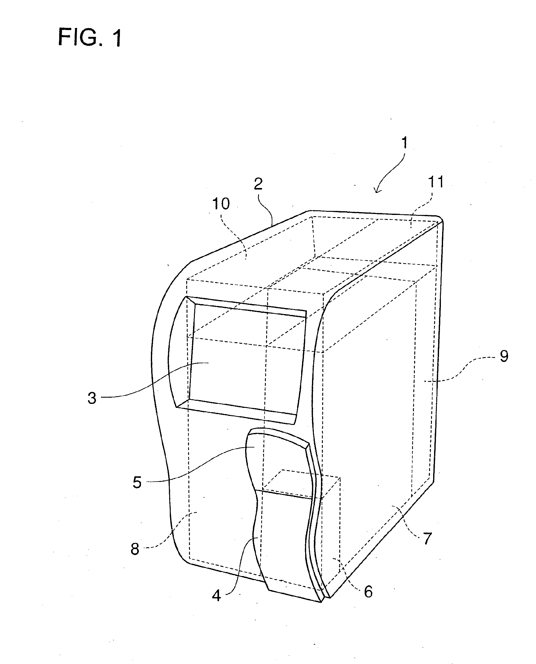
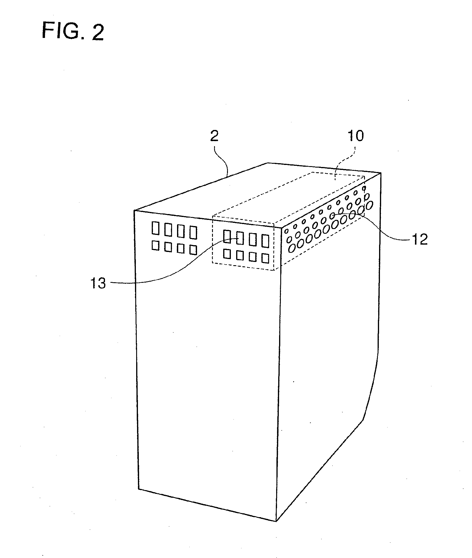
[0114]FIGS. 1 and 2 are a front perspective view and a rear perspective view, respectively, of a blood analyzer according to the embodiment of the invention.

[0115] As shown, an analyzer body 1 is housed in a housing 2, and includes a display section 3 provided on a front upper portion of the housing 2, a sample setting panel 4 provided on a lower front right portion of the housing 2 and to be opened and closed when a sample vessel is set, and a button 5 to be pressed for opening the sample setting panel 4.

[0116] A sample setting section 6 for receiving the sample vessel, and a detecting section 7 for quantitatively dispensing a sample from the sample vessel, diluting the sample and preparing an analysis sample are provided inward of a right side plate of the housing 2...


PUM

PropertyMeasurementUnit
lengthaaaaaaaaaa
outer diameteraaaaaaaaaa

Abstract

A sample analyzer includes a liquid aspirator to be stuck into the closed container for aspirating a sample from a closed container; a preparing section for preparing an analysis sample using the aspirated sample; and an analyzing section for analyzing the prepared analysis sample; the liquid aspirator including an elongated pipe, the pipe having a liquid flow path extending therein and a plurality of communicating sections provided in an outer surface thereof, at least one of the communicating sections communicating between an inside and an outside of the container when the pipe is stuck into the container.

Description

CROSS-REFERENCES TO RELATED APPLICATIONS [0001] This application is a Divisional of co-pending application Ser. No. 10 / 713,302, filed on Oct. 23, 2007, the entire contents of which are hereby incorporated by reference and for which priority is claimed under 35 U.S.C. § 120. [0002] This application is related to Japanese Patent Application Nos. 2002-334243 (filed on Nov. 18, 2002), 2002-334251 filed on Nov. 18, 2002), 2002-334272 filed on Nov. 18, 2002), 2002-334286 (led on Nov. 18, 2002), 2002-334293 filed on Nov. 18, 2002), and 2003-193715 (filed on Jul. 8, 2003) whose priorities are claimed under 35 U.S.C. § 119, the disclosures of which are incorporated by reference in their entirety.BACKGROUND OF THE INVENTION [0003] 1. Field of the Invention [0004] This invention relates to a sample analyzer for analyzing a blood sample, a urine sample and the like and its components used therein and, particularly, to a versatile and portable sample analyzer. [0005] 2. Description of Related Ar...

Claims


Application Information

Patent Timeline
Patent Type & Authority Applications(United States)
IPC IPC(8): B01J19/00B01L11/00B01L3/02B01L9/06B01L99/00G01N1/00G01N15/00G01N15/10G01N15/12G01N35/10
CPCB01L3/02B01L9/06B01L2200/143G01N15/1218G01N35/1004G01N35/1016G01N2035/1032G01N2015/0073G01N2015/008G01N2015/0084G01N2015/1062G01N2035/1018G01N35/1079G01N2015/018G01N2015/012G01N2015/016G01N15/13G01N2015/1024
Inventor FUKUJU, TOSHIKATSUNAGAI, TAKAAKIKANEKO, SHUHEITAKAOKA, HIDENARIYOSHIDA, NORIYOSHIYOSHIDA, TAKASHI
Owner SYSMEX CORP
Learn More