Apparatus For A Shot Peening Treatment

a technology for peening and apparatus, which is applied in the field of apparatus for treating objects, can solve the problems of time and effort, increased height of the apparatus disclosed in these publications, and large space needed to install the blasting machine, so as to achieve the effect of easy transportation

Active Publication Date: 2008-03-20
SINTOKOGIO LTD
View PDF5 Cites 16 Cited by
  • Summary
  • Abstract
  • Description
  • Claims
  • Application Information

AI Technical Summary

Benefits of technology

[0007] Therefore, the object of the present invention is to provide an apparatus for a shot-peening treatment that is compact suc...

Problems solved by technology

However, there is a problem in that the height of the apparatus disclosed in these publications is increased because a large circulation system is needed to collect the projected shot particles from the shot-peening device.
Accordingly, a large space is needed to install the blasting machine.
Because the pit is located beneath the level of the floor or base on which the machine is to be installed, time and effort is necessary to construct such a pit.
Similarly, because the conventional blasting-machine is designed...

Method used


Image

  • Apparatus For A Shot Peening Treatment
  • Apparatus For A Shot Peening Treatment
  • Apparatus For A Shot Peening Treatment

Examples


first embodiment

The First Embodiment

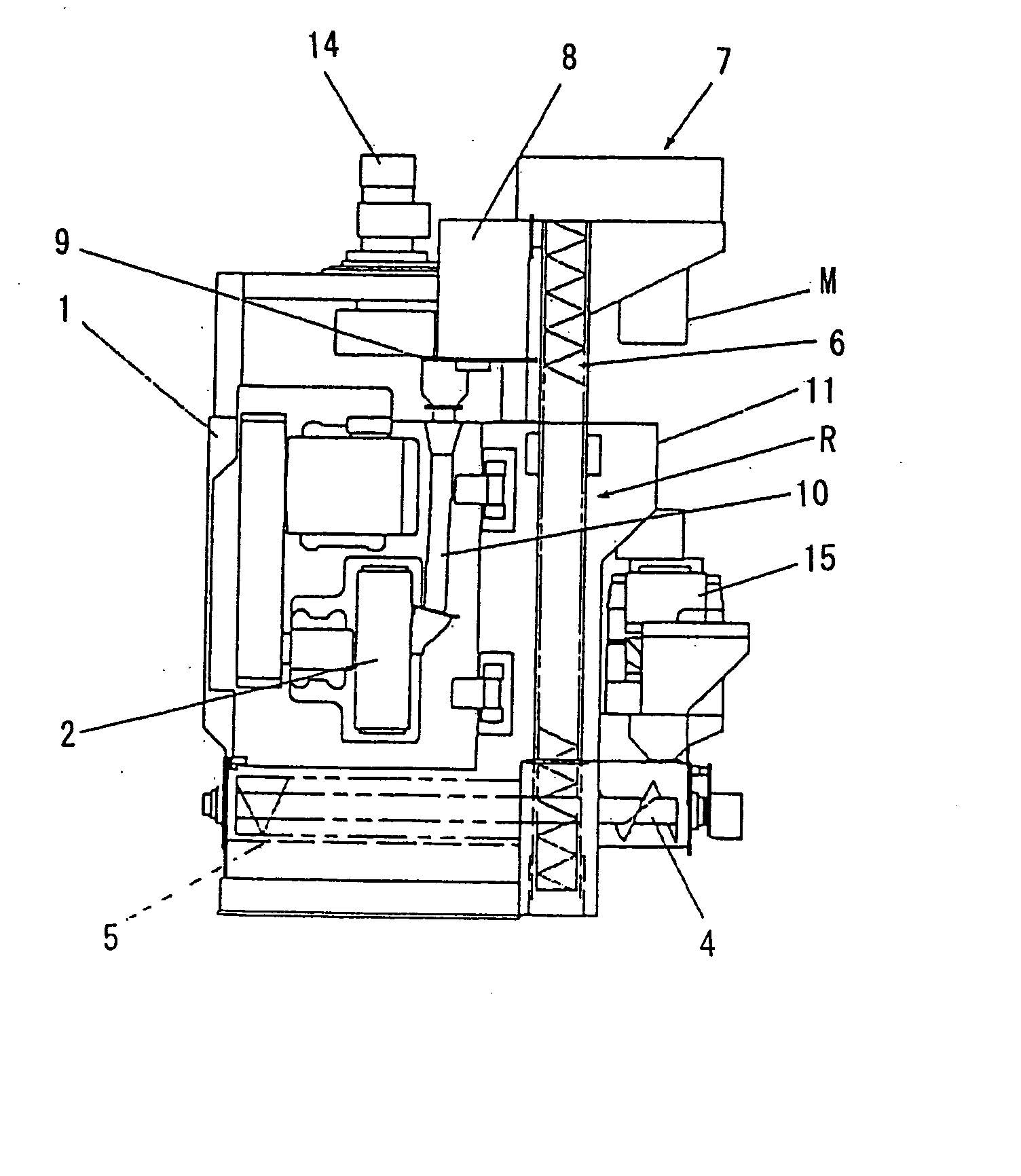
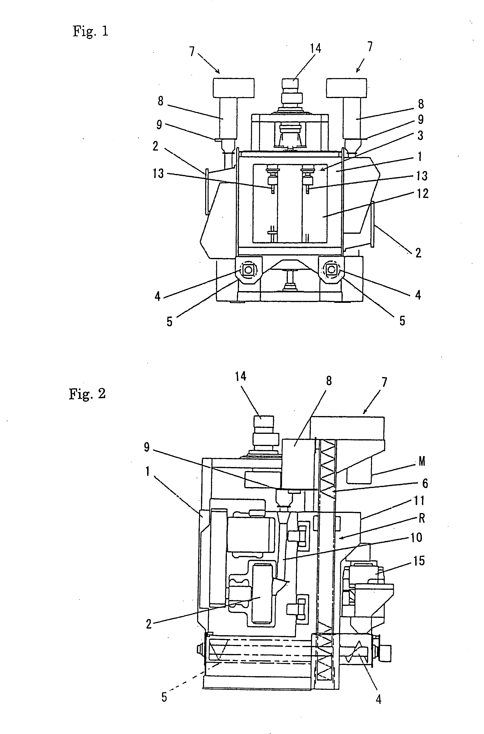
[0038]FIGS. 1 and 2 show a shot-blasting machine as the first embodiment of the shot-peening treating system of the present invention. The shot-blasting machine includes a cabinet (or housing) 1 defining a projection chamber therein and two impeller type shot peening devices 2 mounted on both sidewalls of the cabinet. Each shot-peening device 2 projects shot particles by means of the centrifugal force of an impeller. The shot-blasting machine also includes a hanger type, movable carriage 3 arranged in a projection chamber to suspend and transport a work piece (for example, a forge, a heat-treatment article) to be treated, and a shot circulation unit to collect the projected shot-particles and return them to the shot-peening devices 2.

[0039] In FIG. 2, the shot circulation unit denoted by R includes a pair of cross feeders or horizontal screw conveyers 4 for feeding the projected shot particles in a horizontal direction such that they are gathered on 1) the corre...

second embodiment

The Second Embodiment

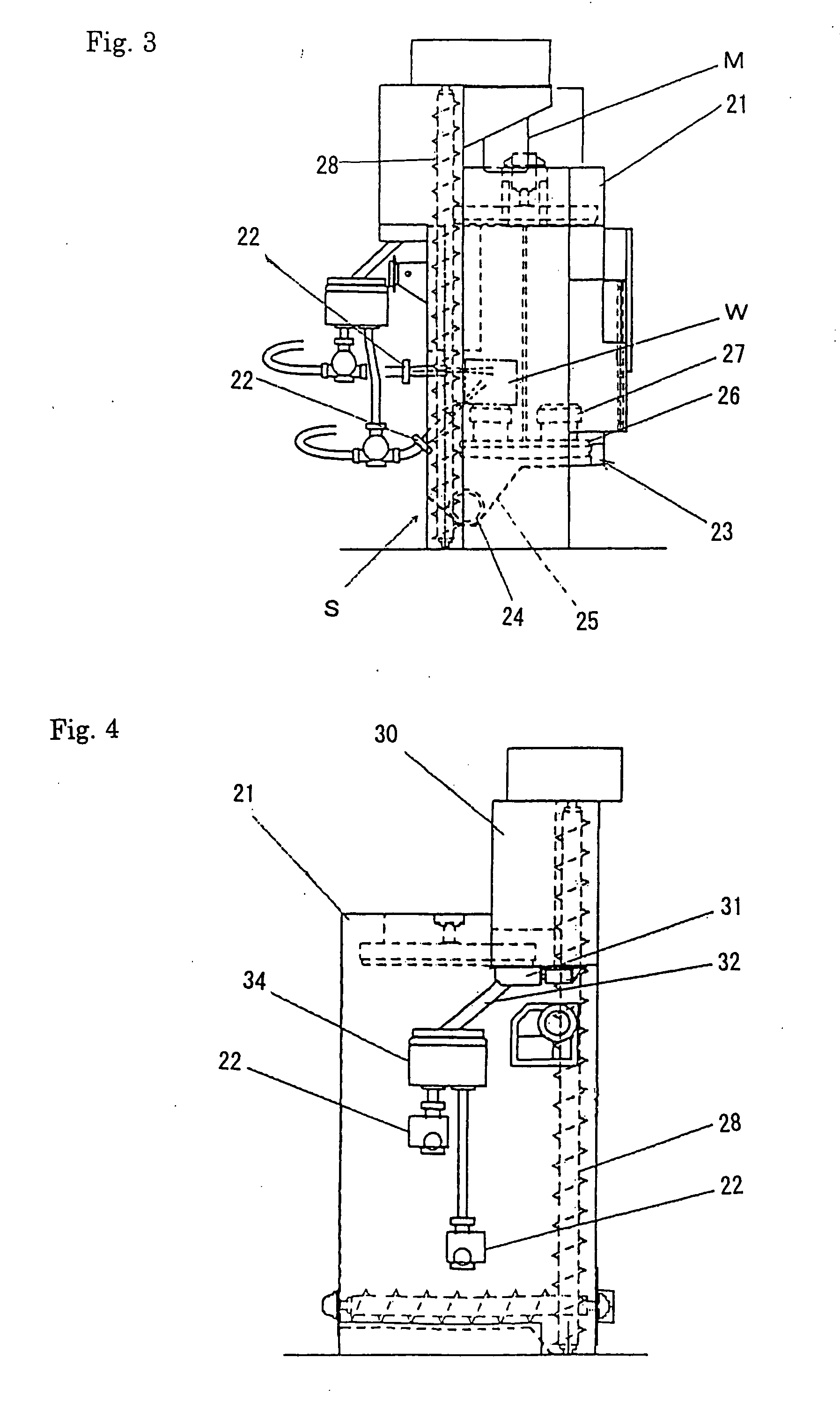
[0056]FIG. 3 shows a cross section of the air-blasting machine of the second embodiment of the present invention. This shot-blasting machine includes a cabinet (or a housing) 21, and two nozzle type shot-peening devices 22 mounted on the opposed sidewalls of the cabinet 21, a table type, movable carriage 23 located within the cabinet 1 for transporting a work piece W, and a circulation unit S for collecting shot particles that are projected to the work piece and for recycling them to the shot peening devices 22.

[0057] Like the cabinet 1 of the first embodiment, a groove 25 having inclined surfaces is provided in the lower part of the cabinet 21 of the second embodiment, to avoid having a pit for the installation of the machine. The second embodiment uses just one groove 25, although the first embodiment uses two grooves 5. In the groove 25, a horizontal cross feeder 24 is received such that the projected shot particles are gathered on one location on the outsid...

third embodiment

The Third Embodiment

[0068]FIG. 6 shows a cross section of the shot-blasting machine of the third embodiment of this invention. This shot-blasting machine includes a cabinet 41, one impeller type shot-peening device 42 mounted on one sidewall of the cabinet 41, a drum type, movable carriage located within the cabinet 41 for supporting and transporting a work piece or work pieces, and a circulation unit T for collecting shot particles that are projected to the work piece and for recycling them to the shot peening device 42. The shot-peening device 42 is not limited to the impeller type. The present invention may constitute, for example, an air-blasting machine using one nozzle-type shot-peening device 22, as illustrated in the second embodiment.

[0069] Similar to the cabinet 21 of the second embodiment, a grove 45 having inclined surfaces is provided in the lower part of the cabinet 41 of this embodiment. Thus a pit for the installation of the machine is not necessary. In this grove, ...


PUM

PropertyMeasurementUnit
Levelaaaaaaaaaa

Abstract

Impeller-type ejectors (2) are installed on the surfaces on both sides of a cabinet (1) defining an ejection chamber in the cabinet. Shots ejected from the ejectors (2) to a workpiece and fallen are conveyed in the horizontal direction by a horizontal screw conveyor (4) positioned above the lower end of the cabinet (1) and then conveyed upward by a vertical screw conveyer (5) whose base end is above the lower end of the cabinet (1). The shots pass from the upper section of the vertical screw conveyer (5) through a chute (8) to reach an opening/closing gate (9). When the gate (9) is opened and the shots are supplied to the ejectors (2) for re-ejection, a portion of the shots is caused to overflow from the gate (9). The overflowed shots are caused to pass through a separator (11) and a sieve device (15) to remove impurities and then returned to the horizontal screw conveyor (4).

Description

FIELD OF THE INVENTION [0001] This invention relates to an apparatus for treating an object with shot particles. BACKGROUND OF THE INVENTION [0002] Shot-peening devices for projecting spherical particles, namely, shot particles, to the surface of a work piece to be treated, are known. Those devices include a nozzle-type device relevant to projecting the shot particles in relatively small volumes (e.g., Japanese Patent Early-Publication 2002-326161, assigned to the applicant) and an impeller-type device relevant to projecting them in relatively large volumes (e.g., Japanese Patent Early-Publication 11-23997). [0003] An apparatus for a projection treatment equipped with a shot-peening device is one such as a shot-blasting machine or an air-blasting machine in which a workpiece is treated. In such an apparatus, the shot-peening device is mounted on a cabinet defining a projecting chamber therein. The shot-peening device projects shot particles to a workpiece that is supported on a mova...

Claims


Application Information

Patent Timeline
IPC IPC(8): B24C3/04B24C9/00
CPCY10T29/479B24C9/006Y02P70/10B24C5/04B24C5/06B24C7/0092
Inventor USHIDA, KOJIISHIKAWA, MITSUOWATANABE, HIROAKIKAGA, HIDEAKIKAWAI, NOBUYOSHIYOKOI, AKIKAZU
Owner SINTOKOGIO LTD
Why Eureka
Try Eureka