Heat sink

a heat sink and heat sink technology, applied in the direction of electrical equipment construction details, lighting and heating equipment, laminated elements, etc., can solve the problems of relative low heat transfer rate, affecting the entire electronic system, and reducing the efficiency of heat dissipation in a limited space to maintain the performance of electronic devices, so as to achieve the effect of minimizing pressure drop and improving heat dissipation

Inactive Publication Date: 2008-03-20
DANAHER MOTION STOCKHOLM AB
View PDF13 Cites 122 Cited by
  • Summary
  • Abstract
  • Description
  • Claims
  • Application Information

AI Technical Summary

Benefits of technology

[0012]An object of the present invention is to provide a heat sink of the kind initially mentioned, wherein the heat dissipation is improved as compared...

Problems solved by technology

When an electronic component within a system overheats, often the entire electronic system is affected.
Therefore, how to effectively dissipate the heat in a limited space to maintain the performance of the electronic devices becomes an important issue.
The use of passive natu...

Method used


Image

  • Heat sink
  • Heat sink
  • Heat sink

Examples


Embodiment Construction

[0034]In the following a detailed description of preferred embodiments of the present invention will be given.

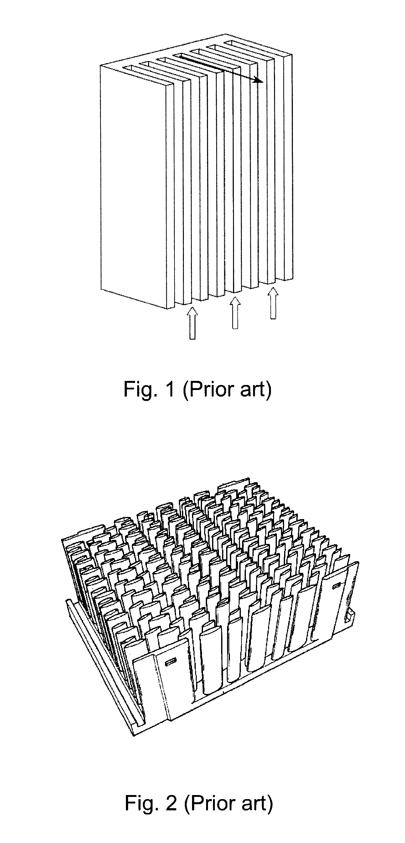
[0035]The prior art heat sinks disclosed in FIGS. 1 and 2 have been discussed in the background section and will not be further discussed herein.

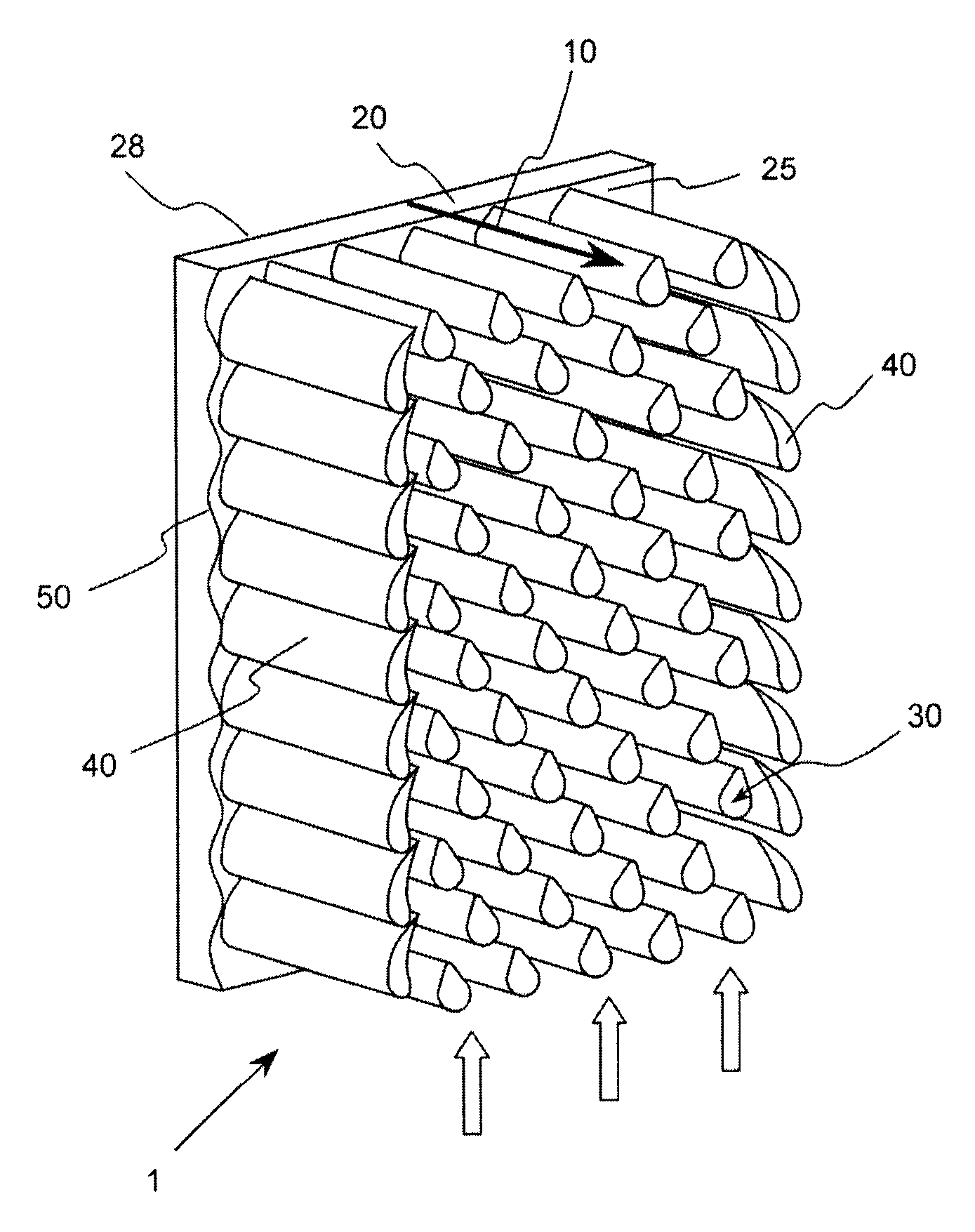
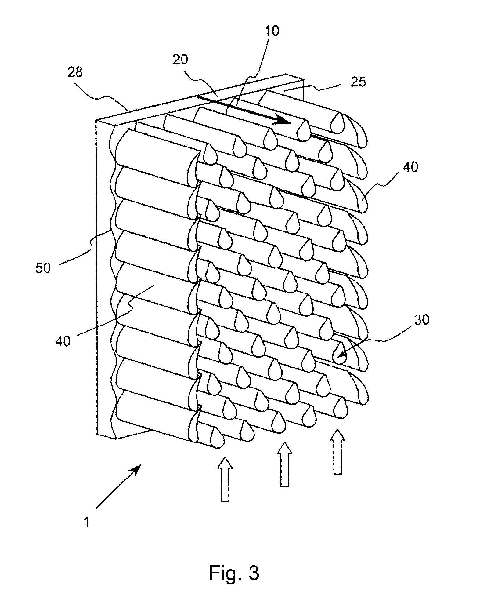
[0036]According to the geometric relationship of the base normal line and the cooling flow direction, two types of heat sinks can be identified: 1) When the cooling flow direction parallel to the base normal line, the heat transfer mode is mainly natural convection. This type of heat sinks is usually orientated horizontally. 2) When the flow direction is perpendicular to the normal line of the heat sink base, either natural convection or forced convection can be applied to the heat sink. This type of heat sinks is usually oriented vertically. The present invention is primarily applied to the second case, i.e., the flow direction is perpendicular to the normal line of the heat sink base.

[0037]FIG. 3 presents a heat sink according to ...


PUM


Abstract

A heat sink comprises a base panel having a top surface and a bottom surface. A plurality of pin fins extend outwardly from the top surface and each fin has a cross-sectional configuration with two radiuses, a first radius and a second radius, wherein the first radius is larger than the second radius. The first and second radiuses are tangentially interconnected by intermediate portions, giving the pin fin cross-sectional configuration a raindrop shape, thereby generating low pressure drop across the heat sink by minimizing the drag force effects and maintaining large exposed surface area available for heat transfer.

Description

FIELD OF INVENTION[0001]The present invention relates to heat sinks in general, and more particularly, to pin fin heat sinks with improved structures for use in dissipating waste heat generated by electronic components and assemblies.BACKGROUND[0002]The exponential increase in the power density of electronic components continues to fuel considerably interest in advanced thermal management of electronic equipment. The ability of an electronic device to maintain within a specific temperature region is directly related to the reliability and performance of the electronic device. Many electronic devices have strict temperature requirements for correct operation and performance. When an electronic component within a system overheats, often the entire electronic system is affected. Therefore, how to effectively dissipate the heat in a limited space to maintain the performance of the electronic devices becomes an important issue.[0003]There are many techniques available to enhance heat dis...

Claims


Application Information

Patent Timeline
IPC IPC(8): H05K7/20
CPCF28F3/022H01L23/3677H01L23/467H01L2924/3011H01L2924/0002H01L2924/00F28F13/12F28F2215/04F28F2250/02
Inventor TONG, WEIBOYLAND, JOHN
Owner DANAHER MOTION STOCKHOLM AB
Why Eureka
Try Eureka