Methods and apparatus for reducing noise via a plasma fairing

a plasma fairing and noise reduction technology, applied in the direction of machines/engines, air-flow influencers, transportation and packaging, etc., can solve the problems of airframe noise, airframe noise now represents a primary noise source, and the free shear layer that results from flow separation is inviscidly unstabl

Inactive Publication Date: 2008-03-20
NOTRE DAME DU LAC THE UNIV OF
View PDF24 Cites 68 Cited by
  • Summary
  • Abstract
  • Description
  • Claims
  • Application Information

AI Technical Summary

Problems solved by technology

A primary component of airframe noise on both takeoff and landing approach is due to the landing gear.
Accordingly, in landing approaches, when engines are throttled down, airframe noise now represents a primary noise source.
Two key sources of airframe noise include landing gear noise associated with flow past landing gear struts, uncovered wheel wells, and undercarriage elements, as well as high-lift system noise associated with trailing flaps, leading edge slats and the associated brackets and rigging.
Free shear layers that result from flow separation are inviscidly unstable.
Consequently, the flow is locally dominated by large-scale, unsteady vorticity that arises as a natural outcome of the rapidly growing instabilities.
Consequently, the flow is locally dominated by large-scale, unsteady vorticity that arises as a natural outcome of these rapidly growing instabilities.
However, passive fairings are limited by practical considerations including the need to allow easy access for gear maintenance and the ability to stow the gear in cruise.
Furthermore, it is oftentimes quite expensive to retrofit such active flow control systems to existing commercial transport aircraft.
Flyover tests have shown that landing gear noise represents a primary source of airframe noise.
The inherent bluff body characteristics of landing gear give rise to large-scale flow separation that results in noise production through unsteady wake flow and large-scale vortex instability and deformation.

Method used


Image

  • Methods and apparatus for reducing noise via a plasma fairing
  • Methods and apparatus for reducing noise via a plasma fairing
  • Methods and apparatus for reducing noise via a plasma fairing

Examples


Embodiment Construction

[0029] The following description of the disclosed embodiment is not intended to limit the scope of the invention to the precise form or forms detailed herein. Instead the following description is intended to be illustrative of the principles of the invention so that others may follow its teachings.

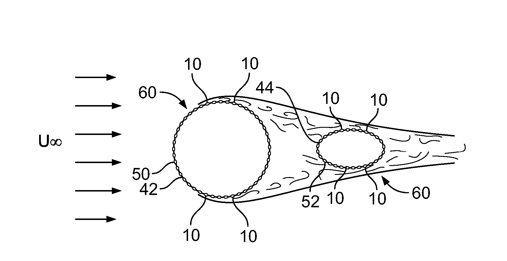
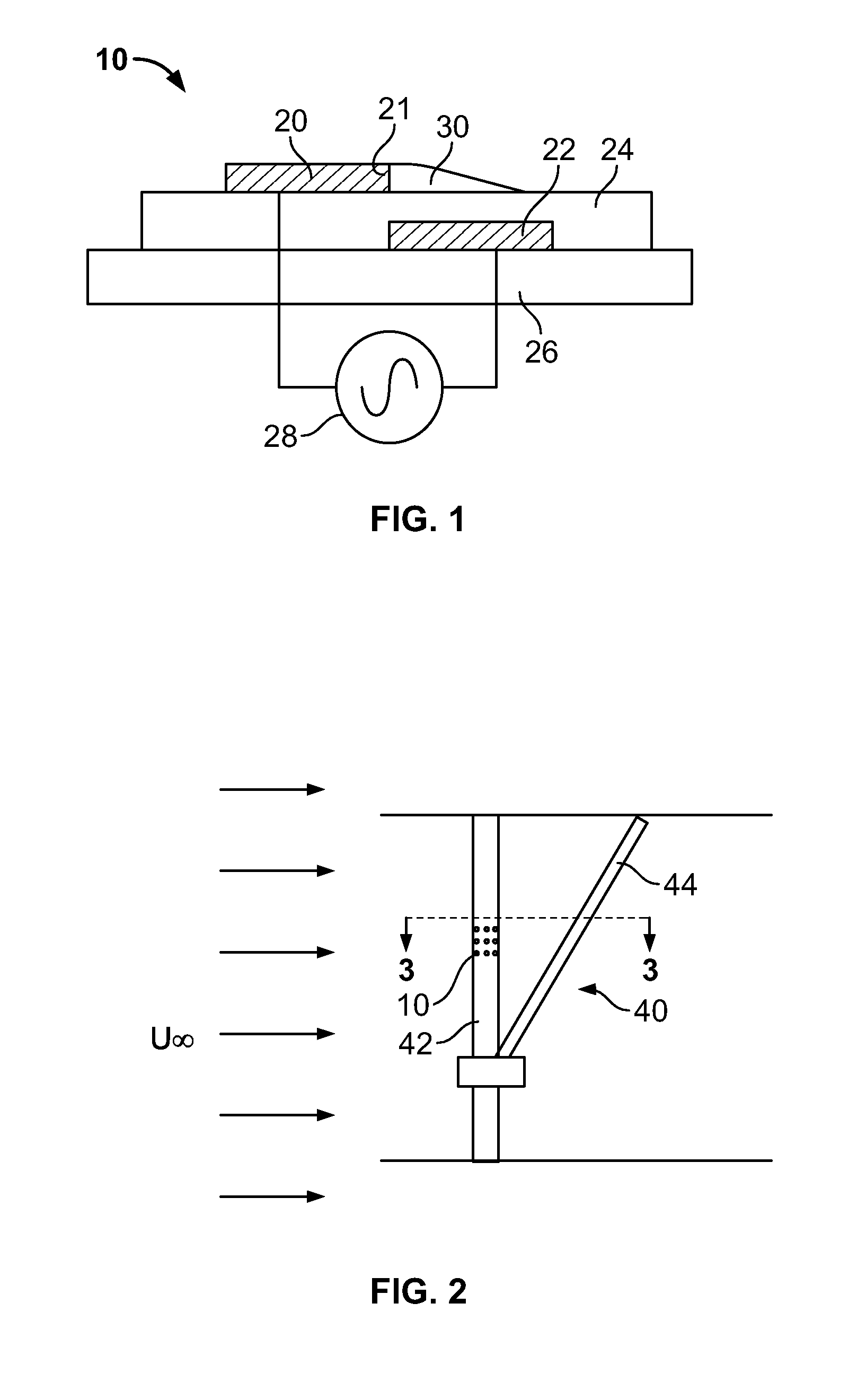
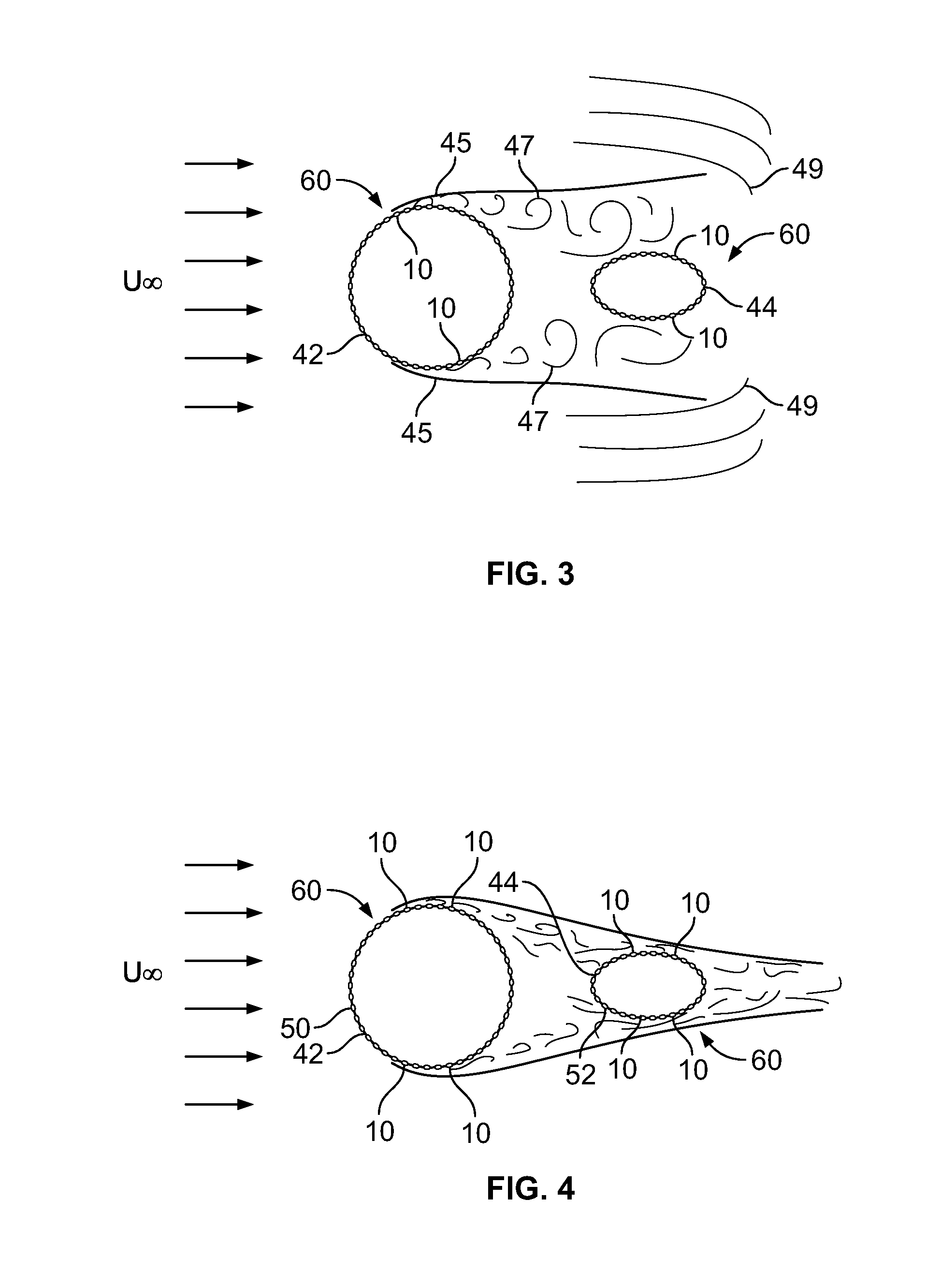
[0030] As described above, it has been suggested from preliminary experiments performed at NASA Ames Research Center and in Europe that faired landing gear generates considerably less noise than corresponding unmodified gear. However, the need to access the gear for maintenance and stow the gear in cruise limits the utility of passive separation control via fairings. In the present disclosure, surface mounted single dielectric barrier discharge plasma actuators are used to create a “plasma fairing” that effectively streamlines the gear by active means. In particular, the SDBD plasma actuators reduce bluff body flow separation that give rise to associated landing gear noise.

[0031] It will...


PUM


Abstract

A plasma fairing for reducing noise generated by, for example, an aircraft landing gear is disclosed. The plasma fairing includes at least one plasma generating device, such as a single dielectric barrier discharge plasma actuator, coupled to a body, such as an aircraft landing gear, and a power supply electrically coupled to the plasma generating device. When energized, the plasma generating device generates a plasma within a fluid flow and reduces body flow separation of the fluid flow over the surface of the body. In another example, the body includes a plurality of plasma generating devices mounted to the surface the body to further aid in noise reduction.

Description

CROSS REFERENCE TO RELATED APPLICATION [0001] This application is a non-provisional application claiming priority from U.S. Provisional Application Ser. No. 60 / 782,137, filed Mar. 14, 2006, entitled “Plasma Fairing for landing gear noise reduction” and incorporated herein by reference in its entirety.GOVERNMENT INTEREST STATEMENT [0002] This disclosure was made, in part, with United States government support from the National Aeronautics and Space Administration, Contract No. NAG1-03076. The United States government has certain rights in this invention.FIELD OF THE DISCLOSURE [0003] The present disclosure relates generally to noise reduction and more particularly to methods and apparatus for reducing noise via a plasma fairing. BACKGROUND OF RELATED ART [0004] A primary component of airframe noise on both takeoff and landing approach is due to the landing gear. In particular, the jet noise component of overall aircraft noise has been significantly reduced by, for example, utilizatio...

Claims


Application Information

Patent Timeline
Patent Type & Authority Applications(United States)
IPC IPC(8): B64C21/00B64C1/40
CPCB64C2025/003F05D2270/172H05H1/24Y02T50/166B64C2230/12B64C23/005B64C25/00B64C2230/14B64C21/00Y02T50/10H05H1/2439
Inventor THOMAS, FLINT O.
Owner NOTRE DAME DU LAC THE UNIV OF
Why Eureka
Try Eureka