
FAIMS electrodes with lateral ion focusing

a technology of lateral ion focusing and electrodes, which is applied in the field of electrometries of faims cells, can solve the problems of no force to prevent ions, d-faims geometry is rather bulky, and the ion residence time is relatively long

Inactive Publication Date: 2008-03-20
THERMO FINNIGAN
View PDF16 Cites 7 Cited by
  • Summary
  • Abstract
  • Description
  • Claims
  • Application Information

AI Technical Summary

Benefits of technology

The patent describes a new type of FAIMS cell that uses a special electrode design to improve the focusing of ions. The cell has two electrodes, with one electrode having a surface feature that helps support the focusing of ions along a specific direction. The cell also has a voltage source that applies a special asymmetric waveform and a direct current compensation voltage to the electrodes. This results in an electric field that helps to focus ions and improve their analysis. The patent also describes a new electrode design that combines the features of a cylindrical and flat-plate geometry to create a more effective ion focusing electrode. Overall, the patent provides new methods and designs for improving the performance of FAIMS cells and their ability to analyze ions.

Problems solved by technology

However, the d-FAIMS geometry tends to be rather bulky and ion residence times are relatively long.
Unfortunately, typically there is no force to prevent the ions from spreading out laterally along the length of the electrodes as they travel through the ion separation region between the electrodes.
Unfortunately, the complexity of the segmented electrode system, including associated voltage supplies and controllers, adds to the complexity and bulk of this otherwise compact design.
A similar problem is encountered in stacked plate geometry FAIMS devices.
Unfortunately, the ions still spread out laterally during the time they spend within the ion separation region between the electrode plates.

Method used


Image

  • FAIMS electrodes with lateral ion focusing
  • FAIMS electrodes with lateral ion focusing
  • FAIMS electrodes with lateral ion focusing

Examples


Embodiment Construction

[0029]The following description is presented to enable a person skilled in the art to make and use the invention, and is provided in the context of a particular application and its requirements. Various modifications to the disclosed embodiments will be readily apparent to those skilled in the art, and the general principles defined herein may be applied to other embodiments and applications without departing from the spirit and the scope of the invention. Thus, the present invention is not intended to be limited to the embodiments disclosed, but is to be accorded the widest scope consistent with the principles and features disclosed herein.

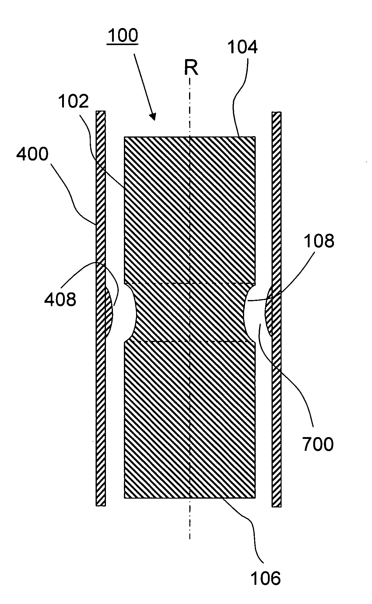
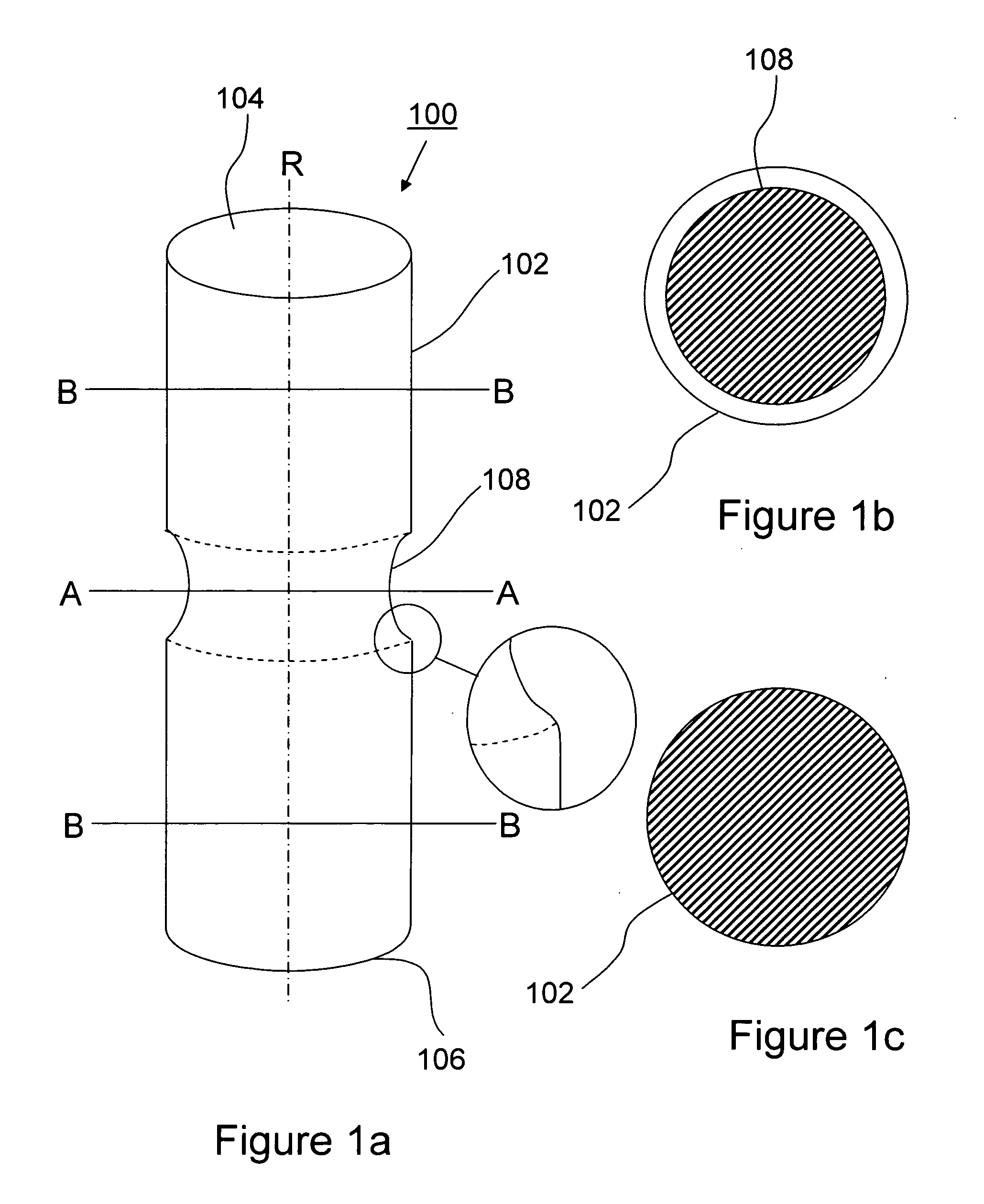
[0030]Referring to FIG. 1a, shown is a simplified side view in partial elevation of a FAIMS inner electrode of right circular cylindrical geometry and adapted with a medial surface feature according to an embodiment of the instant invention. In the specific example that is shown in FIG. 1a, the inner electrode 100 is rotationally symmetric about ...


PUM


Abstract

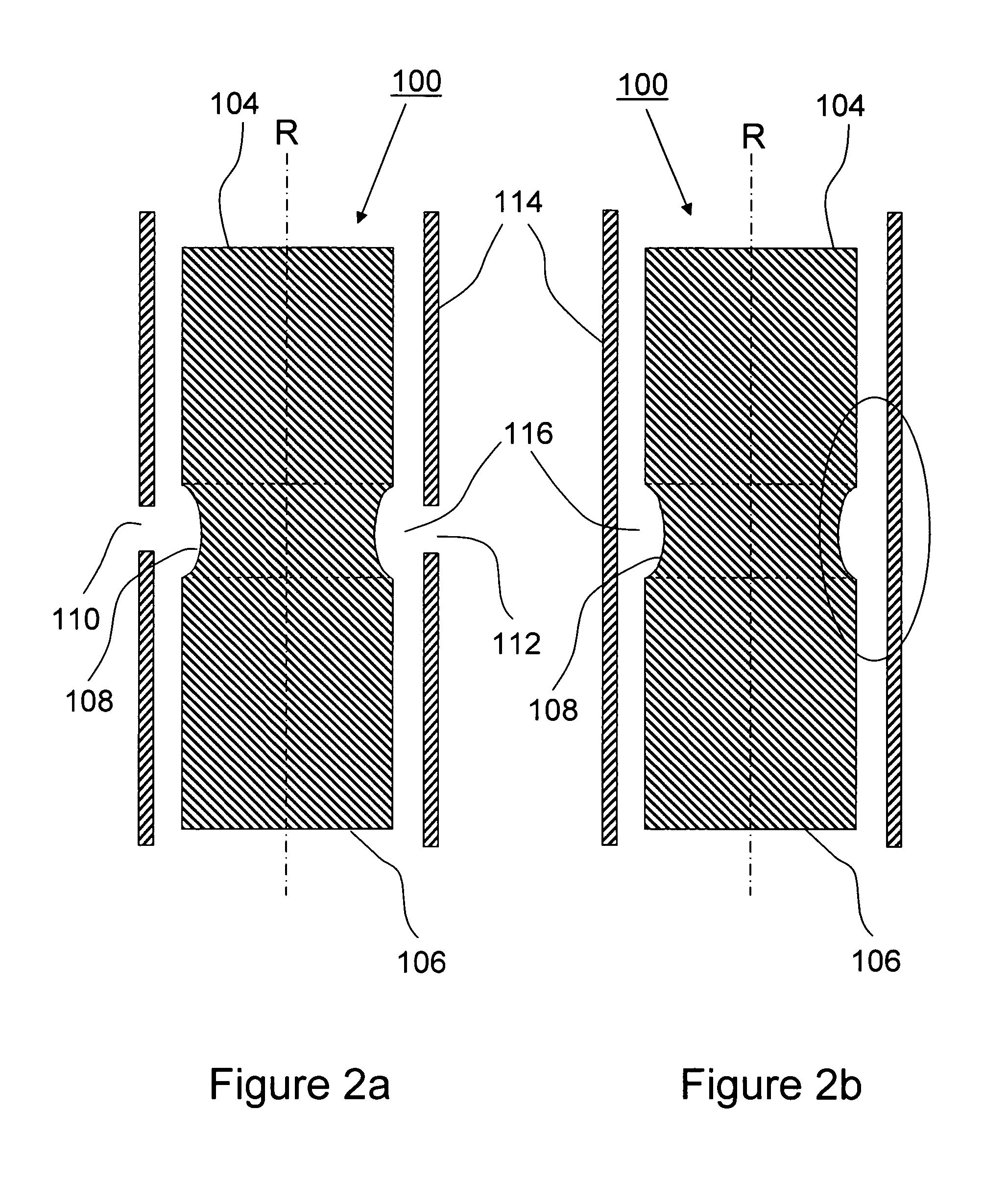
A FAIMS cell including one of side-to-side cylindrical geometry electrodes and stacked-plate electrodes is adapted with a medial surface feature for focusing ions along a lateral direction within an ion separation region of the FAIMS cell. The medial surface feature is provided as one of a recessed channel within an electrode surface and a protruding ridge extending from an electrode surface. The medial surface feature is aligned with a defined aggregate direction of ion travel within the ion separation region for focusing ions along the lateral direction in opposition to the tendency of ions to spread out as a result of space charge repulsion, ion-ion repulsive forces, diffusion and gas flows. The electrical field and fluid dynamic effects produced by the medial surface feature beneficially affect ion transmission efficiency through the FAIMS cell.

Description

FIELD OF THE INVENTION[0001]The instant invention relates generally to High Field Asymmetric Waveform Ion Mobility Spectrometry (FAIMS), and more particularly to electrode geometries for FAIMS cells.BACKGROUND OF THE INVENTION[0002]High Field Asymmetric Waveform Ion Mobility Spectrometry (FAIMS) is a technology that is capable of separating gas-phase ions at atmospheric pressure. In FAIMS the ions are introduced into an analyzer region across which an radio frequency (RF) waveform is applied such that the ions are alternately subjected to high and low electric fields. The waveform is asymmetric; the high field is applied for one time unit followed by an opposite-polarity low field component applied for twice as long. The field-dependent change in the mobility of the ions causes the ions to drift towards the walls of the analyzer region. Since the dependence of ion mobility on electric field strength is compound specific, this leads to a separation of the different types of ions one ...

Claims


Application Information

Patent Timeline
Patent Type & Authority Applications(United States)
IPC IPC(8): H01J49/28
CPCH01J49/42
Inventor BELFORD, MICHAEL W.
Owner THERMO FINNIGAN
Learn More