Circuit structure for LCD backlight

a circuit structure and backlight technology, applied in the direction of electric variable regulation, process and machine control, instruments, etc., can solve the problems of reducing the lifetime of the ccfl, ccfl currents may not be balanced, and non-uniform brightness

Inactive Publication Date: 2008-03-20
O2 MICRO INT LTD
View PDF12 Cites 25 Cited by
  • Summary
  • Abstract
  • Description
  • Claims
  • Application Information

AI Technical Summary

Benefits of technology

[0012]A disclosed circuit structure includes a transformer, a current balance circuit and electronic loads. The transformer is designed to ignite and run the electronic loads. The current balance circuit may be composed of chokes and coupled to low voltage sides of the electronic loads. The current balance circuit is designed to be able to balance current of N electronic loads by using N / 2-1 chokes. The circuit structure may further include a protection circuit that is coupled to the low voltage side of the electronic loads for protecting the circuit structure from an open or broken lamp condition or a short-circuit condition.

Problems solved by technology

This configuration has the well-known problem that CCFL currents may not be balanced owing to the lamp voltage variation and the constant voltage load characteristic of the CCFLs.
The imbalance of CCFL currents causes a reduced lifetime of the CCFL and non-uniformity of brightness.
Though the parallel connection at the transformer primary side as illustrated in FIG. 1 may minimize the effect of the lamp voltage variation, which in turn improves the current balance, some drawbacks may impact the performance / cost of the configuration shown in FIG. 1.
One drawback lies in that due to the tremendous number of transformers 130A to 130N, the circuit 100 will have an increased cost compared with the configuration of direct parallel connection of the CCFLs.
The elements capable of enduring such a high voltage are usually expensive and consequently the overall cost is increased.
Another drawback lies in that the protection circuit 150 as represented in FIG. 1 is complicated, and the complexity of the protection circuit 150 will become problematic as the number of lamps increases.
In FIG. 2A, the common-mode chokes 250A to 250(N-1) are respectively connected to the high voltage sides HV1 to HVN of the CCFLs and therefore these common-mode chokes may have a high cost and require extra attention in applications.
Though the circuits in FIGS. 2A and 2B may provide a solution to lamp current balance, they fail to overcome the drawbacks relative to circuit protection.

Method used


Image

  • Circuit structure for LCD backlight
  • Circuit structure for LCD backlight
  • Circuit structure for LCD backlight

Examples


Embodiment Construction

[0027]Reference will now be made in detail to embodiments of the present invention. While the invention will be described in conjunction with the embodiments, it will be understood that they are not intended to limit the invention to these embodiments. On the contrary, the invention is intended to cover alternatives, modifications and equivalents, which may be included within the spirit and scope of the invention as defined by the appended claims.

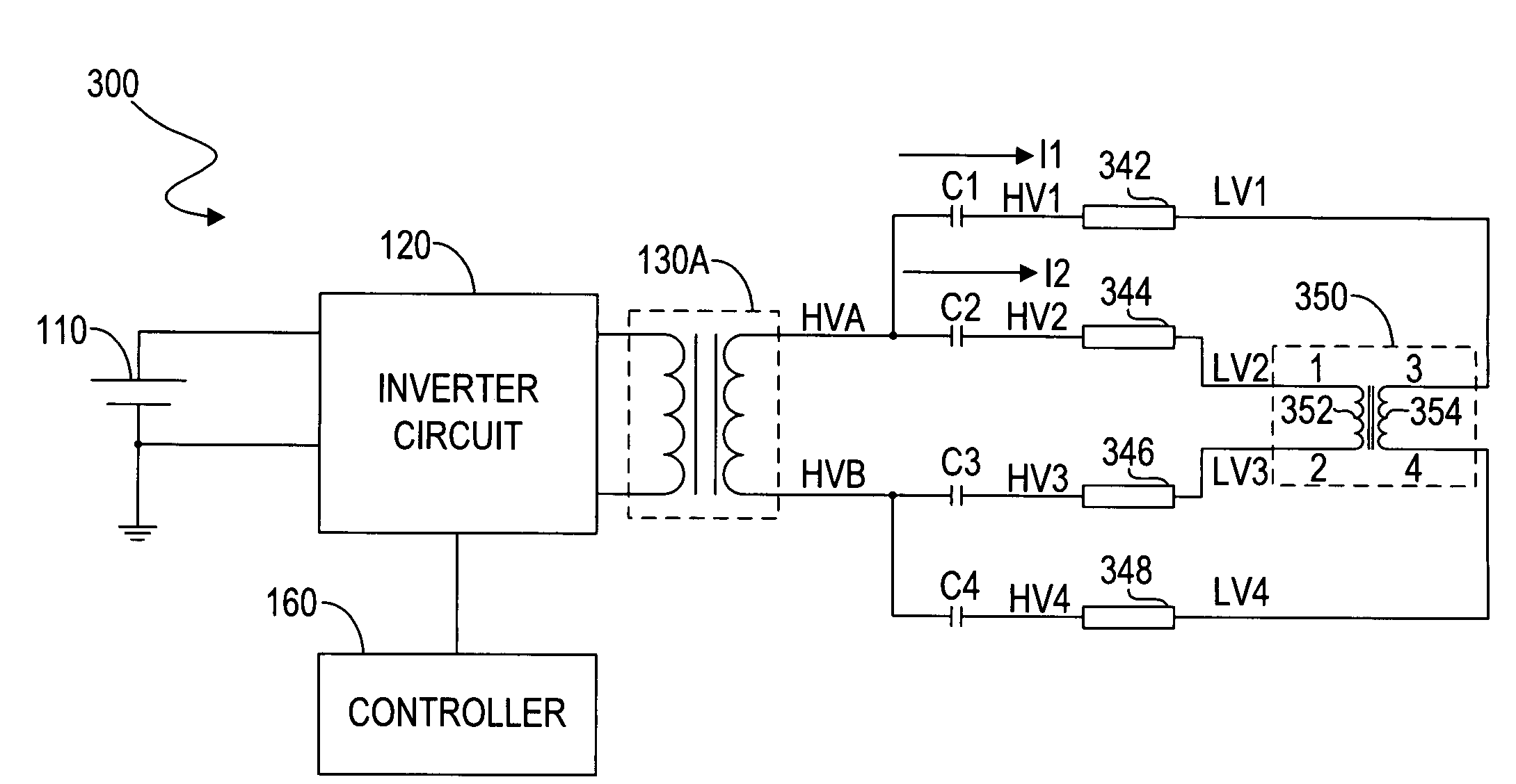
[0028]FIG. 3 illustrates a schematic diagram of a circuit 300 according to one embodiment of the present invention. The circuit 300 is used for driving CCFLs 342, 344, 346 and 348. Besides the DC power source 110, the inverter circuit 120, the transformer 130A and the controller 160, the circuit 300 further includes a current balance circuit consisting of a balance choke 350, typically a common-mode choke. The high voltage sides HV1 and HV2 of the CCFLs 342 and 344 are connected to the high voltage side HVA of the transformer 130A respectiv...


PUM


Abstract

A circuit structure for LCD backlight is disclosed in the present invention. The circuit structure includes an inverter topology, a current balance circuit, and a plurality of loads. The current balance circuit is coupled to the plurality of loads and capable of balancing current of N loads by using N / 2-1 balance chokes. The circuit structure may further include a protection circuit which is coupled to the low voltage sides of the plurality of loads. The protection circuit is capable of sensing lamp voltages and providing a feedback signal to a controller. Furthermore, the protection circuit is composed of count-reduced and cost-competitive electronic elements.

Description

RELATED APPLICATION[0001]This application claims the benefit of U.S. Provisional Application No. 60 / 845,783, filed on Sep. 18, 2006, the specification of which is hereby incorporated in its entirety by reference.BACKGROUND OF THE INVENTION[0002]1. Field of the Invention[0003]The present invention relates to a backlight circuit, and more particularly to a liquid crystal display (LCD) backlight circuit with multiple lamps.[0004]2. Description of the Related Art[0005]LCD panels are used in various applications ranging from portable electronic devices to fixed location units, such as video cameras, automobile navigation systems, laptop PCs and industrial machines. The LCD panel itself cannot emit light but must be back lighted by a light source. The most commonly used backlight source is a cold-cathode fluorescent lamp (CCFL). Usually, a high alternating current (AC) signal is required to ignite and run the CCFL. To generate such a high AC signal from a direct current (DC) power source,...

Claims


Application Information

Patent Timeline
IPC IPC(8): H05B37/02H02H9/00
CPCH05B41/2822
Inventor WANG, XIAOJUNLEE, SHENG-TAILI, YOULINGLIU, DAGUO, RU
Owner O2 MICRO INT LTD
Why Eureka
Try Eureka