Positioning device, method of controlling positioning device, and recording medium

a positioning device and positioning method technology, applied in instruments, wave based measurement systems, computations using denominational number representations, etc., can solve the problems of deteriorating reliability of expected position and average position, and deteriorating accuracy of located position

Inactive Publication Date: 2008-03-20
SEIKO EPSON CORP
View PDF3 Cites 26 Cited by
  • Summary
  • Abstract
  • Description
  • Claims
  • Application Information

AI Technical Summary

Problems solved by technology

However, when the signal from the GPS satellite reaches the GPS receiver after being reflected by a building or the like, or the signal strength is weak, or the dilution of precision (DOP) of the GPS satellite in the sky is low, the located position may differ from the true position to a large extent, whereby the accuracy of the located p...

Method used


Image

  • Positioning device, method of controlling positioning device, and recording medium
  • Positioning device, method of controlling positioning device, and recording medium
  • Positioning device, method of controlling positioning device, and recording medium

Examples


first embodiment

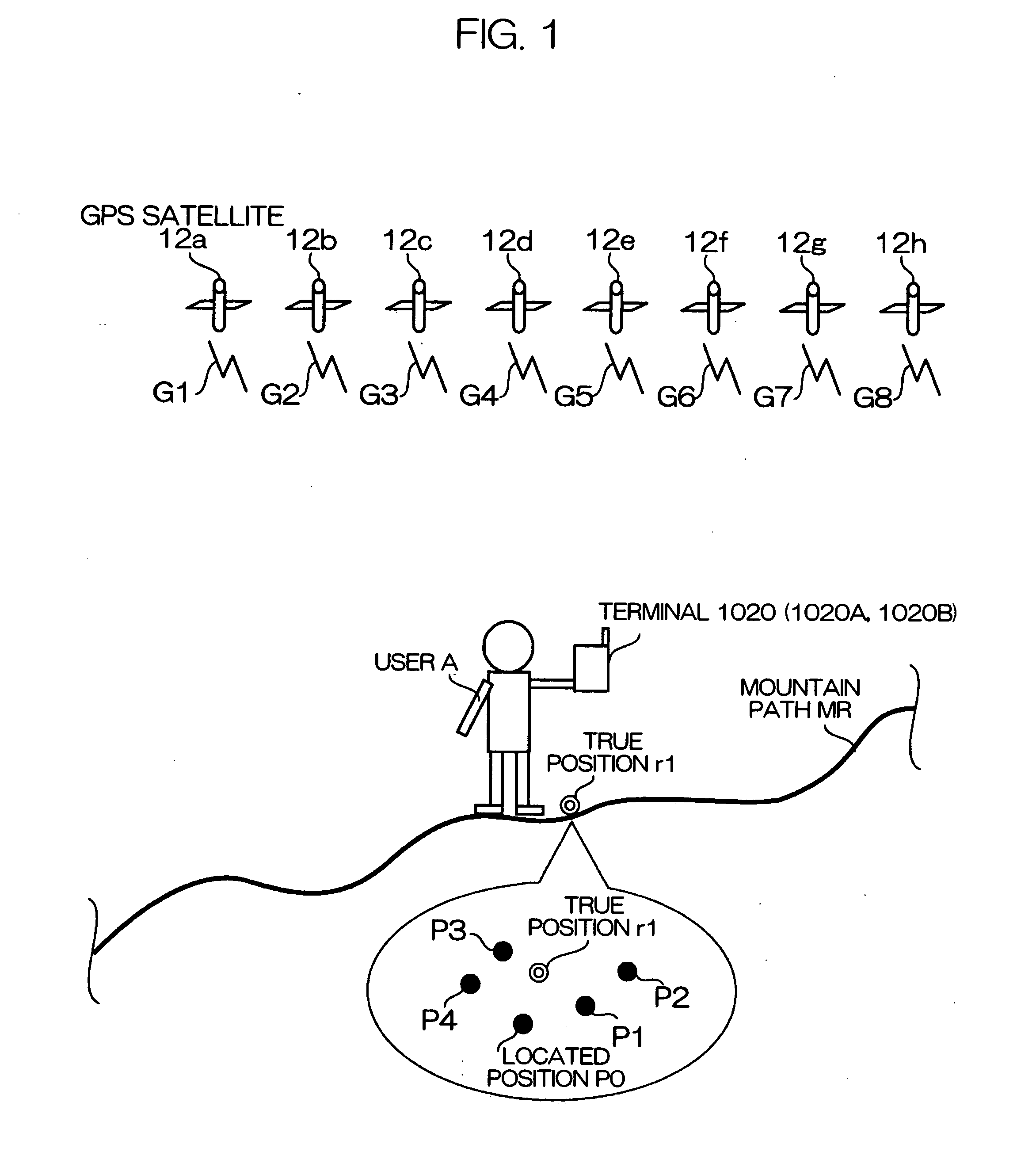
[0138]FIG. 1 is a schematic view showing a terminal 1020 and the like according to a first embodiment of the invention.

[0139] As shown in FIG. 1, the terminal 1020 is held by a user A. The terminal 1020 can receive signals G1, G2, G3, G4, G5, G6, G7, and G8 from GPS satellites 12a, 12b, 12c, 12d, 12e, 12f, 12g, and 12h (positioning satellites), for example. The signals G1 and the like exemplify satellite signals. The terminal 1020 exemplifies a positioning device.

[0140] The user A remains stationary on a mountain path MR. For example, the user A has met with an accident and awaits rescue. The terminal 1020 also remains stationary. The true position of the terminal 1020 is a position r1. The terminal 1020 can allow the user A to be reliably rescued by outputting a position close to the true position r1 as much as possible in a state in which the terminal 1020 actually remains stationary.

[0141] However, the GPS satellite 12a and the like move in the satellite orbits, and the recept...

first modification

of First Embodiment

[0238] A first modification of the first embodiment is described below. The configuration of a terminal 1020A (see FIG. 1) according to this modification is similar to the configuration of the terminal 1020 according to the first embodiment. Therefore, the same sections are indicated by the same symbols, and description thereof is omitted. The following description mainly focuses on how the terminal 1020A differs from the terminal 1020 according to the first embodiment.

[0239]FIG. 11 is a view showing the velocity threshold value β, the distance threshold value y, and the like of the terminal 1020A.

[0240] In the terminal 1020A, the velocity threshold value β is set at 0.5 meters per second (m / s) in an intense electric field, as shown in FIG. 11. The velocity threshold value β is set at 0.75 meters per second (m / s) in an intermediate electric field. The velocity threshold value β is set at 2 meters per second (m / s) in a weak electric field.

[0241] The intense elec...

second modification

of First Embodiment

[0261] A second modification of the first embodiment is described below. The configuration of a terminal 1020B (see FIG. 1) according to the second modification is similar to the configuration of the terminal 1020 according to the first embodiment. Therefore, the same sections are indicated by the same symbols, and description thereof is omitted. The following description mainly focuses on the difference from the terminal 1020 according to the first embodiment.

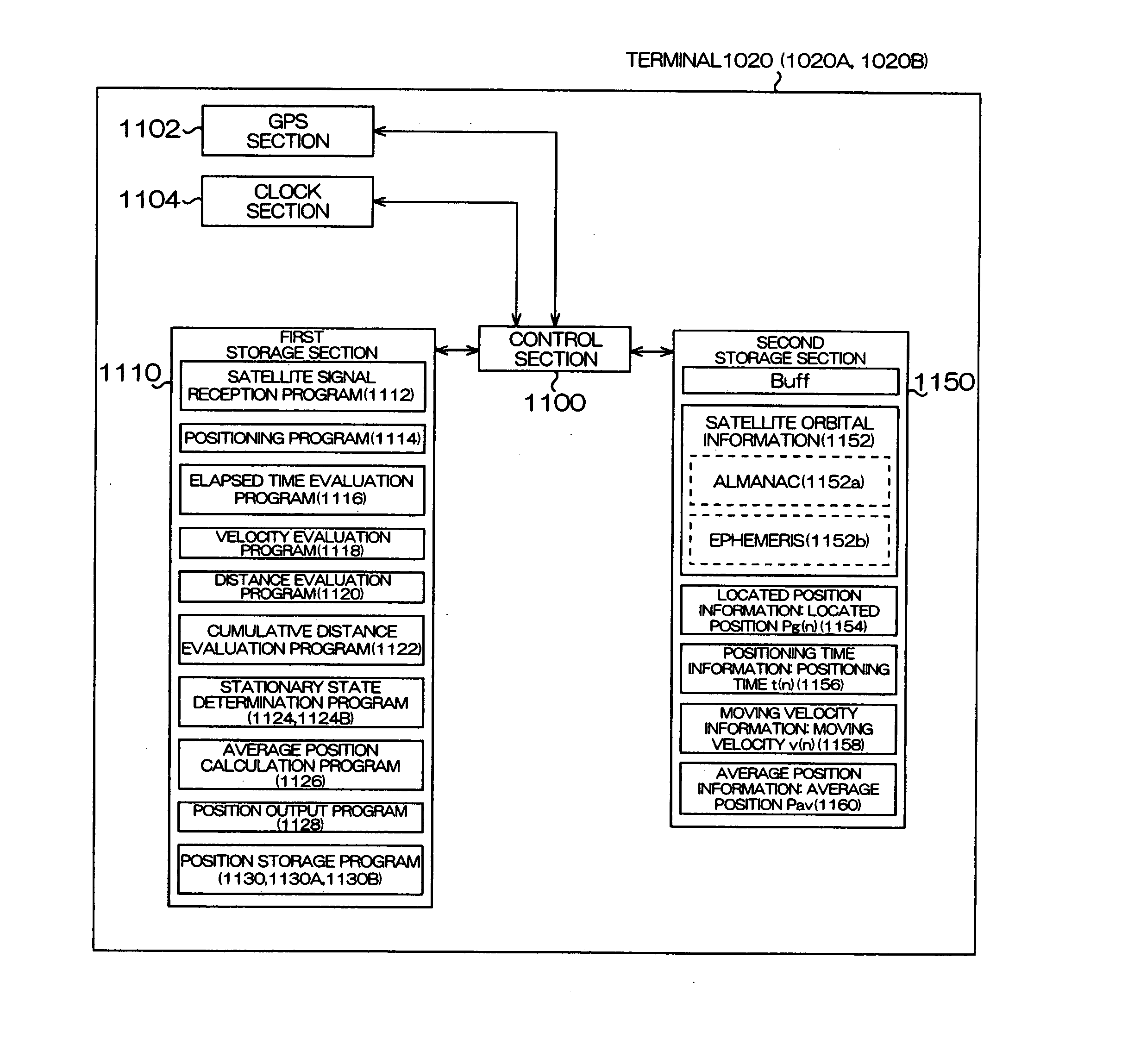
[0262]FIG. 15 is a view illustrative of the process based on a position storage program 1130B (see FIG. 3) stored in the first storage section 1110 of the terminal 1020B.

[0263] The position storage program 1130B functions during multi-shot positioning (see FIG. 5B).

[0264] As shown in FIG. 15A, ten positions P are held in the buffer Buff. When the terminal 1020B has started multi-shot positioning in this state, the control section 1100 stores the average position Pav (stable position Pst) initially calcula...


PUM


Abstract

A positioning device, which locates a position based on satellite signals which are signals from positioning satellites, includes a position holding section which holds a reference position P, a stationary condition determination section which determines whether or not the reference position P satisfies stationary conditions B, an average position calculation section which averages the reference position P satisfying the stationary conditions B and a present located position Pg calculated by positioning to calculate an average position Pav, a position output section which outputs the average position Pav, and a position storage section which stores the average position Pav in the position holding section as the reference position P.

Description

[0001] Japanese Patent Application No. 2006-148834 filed on May 29, 2006 and Japanese Patent Application No. 2006-198759 filed on Jul. 20, 2006, are hereby incorporated by reference in their entirety. BACKGROUND OF THE INVENTION [0002] The present invention relates to a positioning device which utilizes signals from positioning satellites, a method of controlling a positioning device, and a recording medium. [0003] A positioning system has been used which locates the present position of a GPS receiver utilizing a global positioning system (GPS) (satellite navigation system) which is an example of a satellite positioning system (SPS). [0004] The GPS receiver receives signals from three or more GPS satellites, and calculates the distance between each GPS satellite and the GPS receiver (hereinafter called “pseudo-range”) from the difference between the time at which the signal is transmitted from each GPS satellite and the time at which the signal reaches the GPS receiver (hereinafter ...

Claims


Application Information

Patent Timeline
IPC IPC(8): G01S1/00G01S5/14G01S19/40G01S19/42
CPCG01S19/42G01S19/40G01S19/36
Inventor MIZUOCHI, SHUNICHI
Owner SEIKO EPSON CORP
Why Eureka
Try Eureka